For simulation purposes in LTSpice, all components have to have a path to ground.
So you can't sim my previous diagram?? That's a shame.
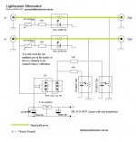
I did it this way to totally isolate the power supply (floated) for the led's, from being coupled in any way to the ldr's themselves.
I think for memory the couple of uV noise floor was looked so slightly better this way.
Cheers George
Last edited:
You can make a Dual Mono (separate L&R volume controls), that way the matching isn't so critical.
Cheers George
George,
I built my second LS and plan to move ahead with Dual mono. Looking at the circuit, did the 100K potentiometers just replaced the trim pots?
BTW, the second LS is good but I am hearing a slight lisp(?) sound particularly with female vocals. Is this attributable to mismatched LDRs (or defective ones)? I am using 8x Eneloop Ni-MH batteries for the time being.
Thanks and cheers
Yes you can omit the trimpots, if your quad matching is close, which is what I do for a Dual Mono Lightspeed Attenuator.
Cheers George
I might be able to simulate the circuit by placing a large resistor between the two grounds.
I was simulating my circuit to see how much attenuation of ripple from the power supply the series shunt regulator would give (about 76dB).
I should probably simulate an LM317 for comparison.
I was simulating my circuit to see how much attenuation of ripple from the power supply the series shunt regulator would give (about 76dB).
I should probably simulate an LM317 for comparison.
George, What parameter you want to see from the sim?
It turns out that the spacing between the LED and Photo-Resistor is not Highly critical. A difference of 2x spacing (0.1" vs 0.2") made less than a 7% change in resistance at 10K for the cell I'm testing, so if this holds true for the GL5516, spacing can be held to +/-.010" the variance in resistance will be a small relative to the variance in the CdS cell resistance characteristic.
NOTE: This was a single sample. Your mileage may vary.
Last edited:
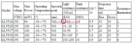
As for using the GL5516 ldr, I tried just about everything but may not this one, if it can get down to 40ohms min resistance like the NSL32SR2S then it will work, if not your minium volume will be too loud for most, essecially owers with high gain sytems and or >100db speakers.
To me from the data specs (attached) it can only do 5kohm min to 500kohm max. This is not low enough.
Cheers George
Attachments
Last edited:
George, What parameter you want to see from the sim?.
If your up to it the noise floor, to see if it correlates with my findings of being better by floating the power for the leds and being isolated from anything to do with the LDR's.
My very first post 2nd pic (which has the typo with anodes of the ldr's and neg rail to chassis ground) then this one.
Cheers George
Attachments
Last edited:
George that is true, if you are making a line attenuator.
I should clarify that I am interested in replacing a dual pot as the volume control for a high input impedance amplifier (Tube).
I've been dissapointed in the poor tracking of dual pots like the Alps Blue velvet pots which are specified at 3dB tracking error.
I'm going to try making a replacement using a single pot to eliminate tracking error and match the couplers to get tighter control.
I've been dissapointed in the poor tracking of dual pots like the Alps Blue velvet pots which are specified at 3dB tracking error.
.
Really?? I've always found a 10kohm dual log Blue Velvet to be excellent trackers, maybe there are fakes?
Why not they copy anything these days that people need and pay good money for.
Cheers George
Look at the spec sheet from Alps. They specify 3dB as the limit. Most are better but some batches push the limits.
If they are within spec, you can't return them. They are what they are.
I think I can do better with hand selecting components and using a single pot for control.
Maybe yes, maybe no.
I'm going to try to see what I can do.
If they are within spec, you can't return them. They are what they are.
I think I can do better with hand selecting components and using a single pot for control.
Maybe yes, maybe no.
I'm going to try to see what I can do.
Last edited:
Hi,
Where can I find 4 matched Silonex NSL32SR2? They need to be shipped to Turkey.
Just need to buy say 20 pieces match them up as I outlined on the first post with a $5 led tester and multi-meter. You'll get maybe 3 quad matched sets, sell the other two sets here. And you'll be in front, with a set for your self.
http://www.diyaudio.com/forums/anal...attenuator-new-passive-preamp.html#post924390
http://tr.farnell.com/advanced-phot...alse&ddkey=http:tr-TR/Element14_Turkey/search
http://ex-en.alliedelec.com/luna-optoelectronics-nsl-32sr2/70136789/
Cheers George
Last edited:
George, from post 1:
Can the top two have a slightly different selection? (I expect yes, because these are sort of independent; the wiper is the dominant factor, there is no balance to zero as such).
With this logic it will give more pairs that will work.
- I want to go 4 channel (active speakers) so above logic makes it simpler for me (just 4 not 8 tight matches..)
- Farneel (I have an account) does not stock 32SR2, delivery times mentioned. Is the device still produced?
- The 32SR3 is available (higher bright/on resistance). This would be a good top device then (as in the strain of above thinking, the two halves don't have to be really similar, it is the wiper that just needs to be turned a few degrees different to get an outcome).
So in fact I can take the schema like GIMP has ("simple SSLV") as a [variable] milliamp source say 2-5 mA and with a specific set mA select which LDR's have the same (within 1%??) resistance, since I have a 5 digit DMM?5th: Is the $5 led tester you can get on Ebay. With this you can quad match your own set of NSL32SR2S(sorted) Silonex led/ldr's you'll need get about 15 pieces to get 2 sets of quad matched led/ldr's for two x stereo Lightspeed Attenuators. So go halves with a buddy and you can have one each.
Match the LDR resistances using a DMM, powering the LED from 1mA to 20mA, give them time as they need a few minutes to warm up.
Can the top two have a slightly different selection? (I expect yes, because these are sort of independent; the wiper is the dominant factor, there is no balance to zero as such).
With this logic it will give more pairs that will work.
- I want to go 4 channel (active speakers) so above logic makes it simpler for me (just 4 not 8 tight matches..)
- Farneel (I have an account) does not stock 32SR2, delivery times mentioned. Is the device still produced?
- The 32SR3 is available (higher bright/on resistance). This would be a good top device then (as in the strain of above thinking, the two halves don't have to be really similar, it is the wiper that just needs to be turned a few degrees different to get an outcome).
The upper device in the attenuator ladder can have a higher resistance.George, from post 1:
So in fact I can take the schema like GIMP has ("simple SSLV") as a [variable] milliamp source say 2-5 mA and with a specific set mA select which LDR's have the same (within 1%??) resistance, since I have a 5 digit DMM?
Can the top two have a slightly different selection? (I expect yes, because these are sort of independent; the wiper is the dominant factor, there is no balance to zero as such).
With this logic it will give more pairs that will work.
- I want to go 4 channel (active speakers) so above logic makes it simpler for me (just 4 not 8 tight matches..)
- Farneel (I have an account) does not stock 32SR2, delivery times mentioned. Is the device still produced?
- The 32SR3 is available (higher bright/on resistance). This would be a good top device then (as in the strain of above thinking, the two halves don't have to be really similar, it is the wiper that just needs to be turned a few degrees different to get an outcome).
Even if the resistance was 100ohms when 10mA was passing, it would make very little difference to the maximum volume from the attenuator.
The lower device does have a significant effect on the minimum and lower volumes. Here a low resistance when 10mA is passing is very useful. It is also important that this low resistance (for the lowers only) is matched otherwise the balance between the stereo channel starts to go way off.
eg.
at maximum volume using 100k control pot and zero trimmers for fine balancing.
upper pair are left 100ohms @ 10mA and right 150ohms @ 10mA
lower pair are left 32k @ 0.03mA and right 33k @ 0.03mA
attenuations: left -0.027dB, right -0.039dB
Those 50ohms and 1000ohms errors give a balance error of only 0.012dB
At near minimum volume
upper pair are left 34k @ 0.03mA and right 35k @ 0.03mA
lower pair are left 48ohms @ 10mA and right 53ohms @ 10mA
attenuations : left -57.017dB, right -56.408dB
Note this time for 5ohms and 1k matching errors the balance is out by 0.608dB
Yes, ten times more accurate matching (5ohms cf 50ohms) but the imbalance goes up 50times from 0.01dB to 0.6dB
It's the lower volume levels that need good resistance matches.
Matching at 2mA, 5mA, 10mA and 20mA does not do much to improve balance at the upper volumes.
But becomes critical for lower volumes where the upper devices are passing <<1mA and the lower devices are passing >1mA
Those regions are where you need to get good matching.
Last edited:
Thanks Andrew.
From this I would expect:
I am of course afraid of misalignment in the whole range in the second case; it could invalidate the whole selection - the selection should be redone with this new pre-load value on the LED.
From this I would expect:
- Adding a few ohms in the one channel with 48 ohms, to earth, would give balance;
- or what I have seen is setting a slightly higher resistor value in front of the LED in the that channel with would create balance by making it a bit darker
I am of course afraid of misalignment in the whole range in the second case; it could invalidate the whole selection - the selection should be redone with this new pre-load value on the LED.
Last edited:
you can trim the balance.
This adjustment will work at one volume setting only, you are likely to find that the balance will still be out at other settings.
I'd suggest you do this trim at the volume setting you use most often. If you select a set of 4 that are close you may find that the balance hardly changes over the range.
You can also adjust the range by adding parallel, or series, resistors, or even both.
This would allow you to match up a pair of channels so that the balance was always slightly to one side, then apply the balance trim to make the two channels virtually identical.
Getting excellent balance over the full range seems to be impossible.
But good balance over a slightly reduced range should be very possible.
One more question.
Maybe go slightly above 5V?
(By George! Nice abstract drawing. I understand this! Yes the two grounds are of different circuits alltogether and don't combine, a different symbol is better for the left part.)
Think about it, could use a 4.8 NiMh volt battery. You claim good results.
With batteries, voltage would differ a bit, e.g. from a nominal 5.1 to 4.4 V.
Ahrgh. Farnell gets its next shipment in October
- Can I just parallel four extra LEDs for two extra channels. It must have been discussed before.
Maybe go slightly above 5V?
(By George! Nice abstract drawing. I understand this! Yes the two grounds are of different circuits alltogether and don't combine, a different symbol is better for the left part.)
Think about it, could use a 4.8 NiMh volt battery. You claim good results.
With batteries, voltage would differ a bit, e.g. from a nominal 5.1 to 4.4 V.
- Is there any impact on the 100R and 100K?
Ahrgh. Farnell gets its next shipment in October
Last edited:
This are the resistance measurements I got using the Kemo tester:
I took the trouble to map these.
I choose a logarithmic scale, but because the MA values should but do not go stepwise on the tester, they create an irregularity in the curve.
Anyway, I see two main groups that behave quite similarly and where I expect that a small matching resistor on the LED will do wonders;
- the whole with only three outliers (25, 10, 2) while I discarded the obvoius wrong ones.

Based on this "review" (spreadsheet soldering comes to mind like spreadsheet management
) there would be more rather good matches than just a few pairs. For example: looking at the bottom end, the No. 3 with only 16 mA max would have the same resistance as no. 22 . . . and that could imply just a small extra resiatance value on the LED.
nice to see that a LED/LDR that is low stays low all the way through the range. Similarly all the others generally stay within that group range, i.e. they track similarly.
There are two obvious exceptions, one high that slopes towards the middle and one low that slopes towards the middle. These two would make bad matches to any others near them.
It looks like you can get many pairs by selecting those that stay near each other. Maybe even get triples or quads if needed.
I am surprised that you did not test down to less than 0.1mA
A 5V supply into a 2Vf LED via a 100k pot gives a minimum current ~0.03mA
You won't do much listening when either LED/LDR is at this current but you will probably use many volume settings that are between 0.1mA and 0.5mA (i.e. when pot has at least one track @ >6k).
Last edited:
- Home
- Source & Line
- Analog Line Level
- Lightspeed Attenuator a new passive preamp