Hi Folks,
This power supply issue is quite simple. The LED requires a steady state current to give a fixed value of light emission. The simple method of feeding the Led from a fixed voltage source via a resistor is fine in theory but the real world is not ideal. Any fluctuation of the voltage from the voltage source will change the current through the resistor thus altering the light emission. If the voltage source is noisy for any reason this noise adds to the voltage source voltage value, causing modulation of the current through the resistor, which in turn, flows into the diode. This will cause modulation of the light output from the LED, which will then cause resistance change in the LDRs in sympathy with the noise voltage waveform. Obviously gross noise modulation will be readily obvious.
An example that might help you understand the resulting effect on the music signal is the effect of adding vibrato to a voice or a musical instrument. The signal level is modulated by a control mechanism, or with a singer by their vocal chord, to give this effect. Applying this effect to the whole music signal would some loose it’s appeal.
Any noise on the power supply would generate this effect but the question is really how much becomes noticeable. This would depend on the resolution of the sound system in use.
Some enthusiasts using my VCCS system (Voltage Controlled Current Source) for driving the LDR LEDs, have been using some of my modified low noise shunt and series regulators to replace the TL431 and the 12 volt three terminal regulator on the VCCS board, with good results. These regulators are much quieter than the TL431, and the 12 volt series regulator. This is now my preferred method of powering the VCCS. I posted details on this thread a while back. The series regulator is very quiet and could easily be used to power the potentiometer-controlled version of the George’s Lightspeed configuration.
Regards
Paul
Well put, Paul.
One thing I thought about doing, but haven't tried yet, is injection of a readily identifiable signal into the LED power supply. Music, for instance. If the power supply is a superior one like yours, there should be no output on the signal side of the LDR. It would be interesting to run the test with multiple power supply versions.
One other thing: everything makes a difference. It may not always be audible, but in addition to circuit design, component choices, cabinet construction, etc. all affect sound. At some point in a system's evolution, resolution often becomes so good that previously masked effects become apparent. Sometimes we compensate for flaws with other flaws. It can be vexing. Experimentation is the only solution, sharing results, good or bad, helps us all.
Equally well put, sepolansky.
There would only be no output on the signal side if the regulator output impedance was absolutely zero at all the test frequencies, as you cannot generate any voltage change across zero impedance no matter how much current you feed into it. I wish I could provide one of these ideal regulators but at this point in time I can’t. Obviously, the lower the output impedance, the better. In practice, with this application, regulator supply line rejection and-self generated noise are key players in the equation too.
Regards
Paul
Hi Folks,
This power supply issue is quite simple. The LED requires a steady state current to give a fixed value of light emission. The simple method of feeding the Led from a fixed voltage source via a resistor is fine in theory but the real world is not ideal. Any fluctuation of the voltage from the voltage source will change the current through the resistor thus altering the light emission. If the voltage source is noisy for any reason this noise adds to the voltage source voltage value, causing modulation of the current through the resistor, which in turn, flows into the diode. This will cause modulation of the light output from the LED, which will then cause resistance change in the LDRs in sympathy with the noise voltage waveform. Obviously gross noise modulation will be readily obvious.
An example that might help you understand the resulting effect on the music signal is the effect of adding vibrato to a voice or a musical instrument. The signal level is modulated by a control mechanism, or with a singer by their vocal chord, to give this effect. Applying this effect to the whole music signal would some loose it’s appeal.
Any noise on the power supply would generate this effect but the question is really how much becomes noticeable. This would depend on the resolution of the sound system in use.
Some enthusiasts using my VCCS system (Voltage Controlled Current Source) for driving the LDR LEDs, have been using some of my modified low noise shunt and series regulators to replace the TL431 and the 12 volt three terminal regulator on the VCCS board, with good results. These regulators are much quieter than the TL431, and the 12 volt series regulator. This is now my preferred method of powering the VCCS. I posted details on this thread a while back. The series regulator is very quiet and could easily be used to power the potentiometer-controlled version of the George’s Lightspeed configuration.
Regards
Paul
Newbie to this thread and there is a LOT to read! Can you point me to info on your VCCS for use with Lightspeed? Thanks.
Newbie to this thread and there is a LOT to read! Can you point me to info on your VCCS for use with Lightspeed? Thanks.
The circuit diagrams are on post 2738, page 274.
Some pics are on post 1874, page 188 and post 2284 page 229.
Prices for printed circuit boards and built and tested modules are on post 1804, page 181. I will have to quote for any carriage charges as these have changed slightly since these were posted.
I hope this helps. The thread is a long read from start to finish!
Regards
Paul
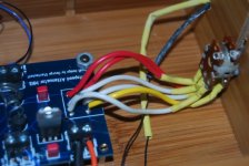
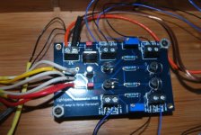
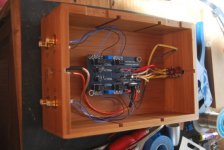
Hi All, I have just completed my second LS, no1 suffered from destroyed LDR´s when soldering. I then destroyed circuit board trying to change them, AHEM. The latest one I took great care with to ensure that it did not suffer the same fate. But, The sound is there in the background, very low, no matter where the volume is set, when I move the pot there is no change. any help with this would be much appreciated.
I believe you have wired the potentiometer incorrectly. When you correct it you will have volume and volume control.
Remember, 5V goes to the connection between the two gangs of the pot. Then remember that on each gang two of the pins must be shorted together.
I think I should stress that 5V must go to where the two gangs meet.
Uriah
Remember, 5V goes to the connection between the two gangs of the pot. Then remember that on each gang two of the pins must be shorted together.
I think I should stress that 5V must go to where the two gangs meet.
Uriah
CLN put your DMM on the long leads of the LDRs and see if they have ANY resistance. What resistance do you get? Turn the pot. Does it change?
Have you verified if you have 0V and 5V going to the right sides of the power input terminal?
Does your wallwart in fact output DC?
Have you verified if you have 0V and 5V going to the right sides of the power input terminal?
Does your wallwart in fact output DC?
Hi All, I have just completed my second LS, no1 suffered from destroyed LDR´s when soldering. I then destroyed circuit board trying to change them, AHEM. The latest one I took great care with to ensure that it did not suffer the same fate. But, The sound is there in the background, very low, no matter where the volume is set, when I move the pot there is no change. any help with this would be much appreciated.
what kinda sound you hearing in the background? Is it noise OR a whisper when the pot is set to minimum.....I'm using the same setup without any problem...
CLN if no resistance is recorded then something is direly (is that a word? ) wrong, which obviously is obvious to you.
Whats wrong I dont know. I dont have that board and cant figure out why you have no reading, which means zero power, from the LDRs. No power is getting to them. Do you have a solder blob somewhere shorting ground to positive? Maybe a pick underneath.
Uriah
Whats wrong I dont know. I dont have that board and cant figure out why you have no reading, which means zero power, from the LDRs. No power is getting to them. Do you have a solder blob somewhere shorting ground to positive? Maybe a pick underneath.
Uriah
Having checked the underside of the board I cant see anything that would cause the problem. This may sound really stupid but I just have to ask, on the diagram for the board I noticed that where the connector blocks sit that all the circuit runs are on the inside except the actual power which appears to be the circuit runs on the outside of the board, if this is true then this would explain why I have no power.Colin.
- Home
- Source & Line
- Analog Line Level
- Lightspeed Attenuator a new passive preamp


