LDR pre
George,
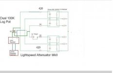
I stricly follow your cicut. Dula100K ( read around 97k).No soldering. Connected with screw terminal. May be damaged piece.
Repalced the shunt LDRs with no problem.
Now question is :-
with 100 Ohms series resister it is showing 25 Ohms and increased to 420 oms to get around 46 ohms. 440 oms is ion shunt ony. Series LDR series resister remain 100 Ohms in both channel.
Question is will this make amy difference in sound or volume compared to 50 ohms LDR and 100 oms series for shunt and series as per your MK II. pLS SEE BELOW. Unforunately he sound was different. Any reason
see file attached.
George,
I stricly follow your cicut. Dula100K ( read around 97k).No soldering. Connected with screw terminal. May be damaged piece.
Repalced the shunt LDRs with no problem.
Now question is :-
with 100 Ohms series resister it is showing 25 Ohms and increased to 420 oms to get around 46 ohms. 440 oms is ion shunt ony. Series LDR series resister remain 100 Ohms in both channel.
Question is will this make amy difference in sound or volume compared to 50 ohms LDR and 100 oms series for shunt and series as per your MK II. pLS SEE BELOW. Unforunately he sound was different. Any reason
see file attached.
Attachments
George,
I stricly follow your cicut. Dula100K ( read around 97k).No soldering. Connected with screw terminal. May be damaged piece.
Repalced the shunt LDRs with no problem.
Now question is :-
with 100 Ohms series resister it is showing 25 Ohms and increased to 420 oms to get around 46 ohms. 440 oms is ion shunt ony. Series LDR series resister remain 100 Ohms in both channel.
Question is will this make amy difference in sound or volume compared to 50 ohms LDR and 100 oms series for shunt and series as per your MK II. pLS SEE BELOW. Unforunately he sound was different. Any reason
see file attached.
Are you able to attain channel balance with the 1k calibration trimpot (only on the louder of the two channels) with all the 4 X 100ohms insitu?
Cheers George
If not then your ldr's are not well matched, I match all 4 at 2.5mA 5mA 10mA and 20mA if you only match up pairs, series and then shunts you will change the progressive feel of the volume control, instead of behaving like a log pot it can come on too fast at the begining and have nothing at the end.
Cheers George
Cheers George
Also as a quick check to see if one of your LDR's has gone west, short out the (1k trimmer) and by adjusting the volume control to get even voltage on the ldr side of the 4 x 100ohm resistors to ground, (you can get this very precise if you have used 1% metal film 100ohm resistors), when you have the exact same voltage then all 4 ldr's should measure similar resistances, if you have a funny one it will be wildly out compared to the other three either the led section has gone or the ldr section has gone.
Cheers George
Cheers George
Last edited:
George,
tank you for your reply. That make sense.
Wen changed from 100 R to 420R in shunt LDR only ( removed the Trim pot)
channel loudness is not quite audible. Looks like almost in the dead centre.
I made another one yesterday wih one more set . expecting I can get 50 ohms without adjustments. But got only 25 Ohms and But Music is audiible even if pwer is removed from the LDR. Will pay hrs will not die
I still I do not know.
Technically is it right to change the value of the shunt LR to get around 50ohms. Is it a compramise.
thanks
George
Thank you for the reply. That is what I aslo thought. Your advise to people like me is quite valuable.
Can you pls let me know why music is audible even when power is removed from the LDR.
The resister behaviour is quite right. I got some improvement changing to a different brand. But not like the sound I got from 50 ohms LDR. unforunately one gone wild.
Can any body let me know where I can get a matched pair with 50 Ohms /1 meg LDrs. I do not want to change the resister value in shunt to get 50 oms.
that is sounding not good to me.
thanks
George
Can you pls let me know why music is audible even when power is removed from the LDR.
thanks
Because the LDR's can never go to complete zero ohms (short) or complete infinity ohms (open circuit).
Cheers George
maximus> A couple of questions about the VCCS...
It would appear the VCCS has been available in a few different incarnations during the history of this thread.
What would it take to modify the circuit for balanced operation using the the most current design?
After doing the mods for balanced operation, would it be ok to run it in regular "unbalanced" mode?
I can't solder surface mounted components so I'm thinking about buying one of your assembled units. How much would that be with shipping and all?
Remote control for the lightspeed MKII configuration.
Hi markusG,
Using the current design you would need to run a parallel set of LDRs for the anti-phase signal on each channel. The LEDs for these LDRs would be wired in series with their counterpart opposite phase LDR LEDs.
This will require re-sizing the power supply voltage regulator, IC3, to 18 volts, increasing the input voltage (pin 7) to 22-24 volts and changing R13 to 10K. Also C3, C6 and C7 will need a voltage rating of 25 volts instead of 16 volts.
You could still run the VCCS in un-balanced mode at these new voltage levels.
The built and tested VCCS module without the LDRs costs £60 and insured carriage and packing to Sweden will cost £9 making a total of £69 to send. You can pay via PayPal by sending funds to paul@paulhynesdesign.com in GBP and please remember to include details of delivery address and what you are ordering.
Matched LDRs are important for phase/anti-phase signal level matching and these are available from Uriah. You can order four matched pairs and rely on the VCCS balance control for channel matching or you can ask Uriah if he would be prepared to set up two sets of matched quads.
Regards
Paul
I am testing LDRs today actually. 480 of them fired up and have been burning in for 72 hours now. Tested 3 different positions so far and will continue to test either 1 or two more positions. Never have tested 5 positions before but my new test fixture is making things way easier, so we will see.
Um, lessee here.. last time I didnt offer balanced. I have before but the last batch didnt produce many balanced sets. I have to wait til I am done with this batch to know how things went. Probably be done with all the testing today or in morning and then I have to work with the spreadsheet for a few days. Give me til middle of next week and shoot me an email about balanced if thats what you are after.
Uriah
I´m pleased of the concept as I´m looking for a passive volume control between my Linn Akurate DS (out 2Vrms, 300Ohms) and my Linkwitz active crossover (in max 0,7V, 10kOhms, www.linkwitzlab.com/orion_asp.htm).
Presently, I do fixed attenuation with a classic voltage divider.


In Lightspeed system , which of the R is changed by LDR? R1 , R2, both?
1) Would your Lightspeed work fine with my system ( 300Ohms Out 10kOhms in) or are there any impairments to be considered?
2) In the future I might want to add remote control via LAN or RS232(out of thr Linn). How would this work with the LDR system?
Presently, I do fixed attenuation with a classic voltage divider.
In Lightspeed system , which of the R is changed by LDR? R1 , R2, both?
1) Would your Lightspeed work fine with my system ( 300Ohms Out 10kOhms in) or are there any impairments to be considered?
2) In the future I might want to add remote control via LAN or RS232(out of thr Linn). How would this work with the LDR system?
It's LDR volume-control 'nirvana'?
Correct me if I'm wrong here... But, although I understand how LDR eliminates (rotary) switch contacts (which is a agood thing), it does not solve the impedance mismatch and energy dissipation issues associated with adding (variable) resistors to the signal path.
I suppose that in an 'ideal' system, LDR could be as close to 'nirvana' as you could get, ideal being: low impedance, high volatge source (CD player); high impedance sink/amp; and short (low capacitance) cable runs (albeit not balanced)... Which probably represents a reasonably large number of systems out there, but certainly not all.
1) Would your Lightspeed work fine with my system ( 300Ohms Out 10kOhms in) or are there any impairments to be considered?
2) In the future I might want to add remote control via LAN or RS232(out of thr Linn). How would this work with the LDR system?
Hi fbee, your xover has probably a fet input opamp at the input stage, if so you can then replace the 10k to ground resistor at the input of the xover to 100k, then all will be fine.
Cheers George
georgehifi @ optusnet.com.auGeorge, I tried to send you an e-mail, but it was rejected by your server.
Could you please PM me another adress? Thanks Frank
Remove the spaces. Frank don't send anything over 400K or it will get rejected
Cheers George
Last edited:
George, the e-mail (only one a few words for testing) just came back again, saying it was blocked. I shaded your adress here:
SMTP error from remote mail server after RCPT TO:XXXXXX.com.au>:
host extmail.optusnet.com.au XXX <XXX.com.au>... Mail from XXXXX blocked using Trend Micro oRBL+
SMTP error from remote mail server after RCPT TO:XXXXXX.com.au>:
host extmail.optusnet.com.au XXX <XXX.com.au>... Mail from XXXXX blocked using Trend Micro oRBL+
LDR pre
Hi all,
thanks to George and Uriah. I made an LDR pre and connected to Mccormack DNA 225 through pioneer CD player and B & W 801 MkII. Analysis Plus speaker cable with my Diy $3 interconnect. Power supply 3 stage regulation. 18 VDC to 12 VDC to 5 VDC.
Smoked my $2400 tube pre amp ( I do not want to mention the brand) and shook the four walls of the listening room. My friend's wife came out from the kitchen and shouted. The best proof of the real sound preasure and recognition. reduced the volume to get a good dinner and avoid expensive divorce.
Thanks to Uriah and George for all their advise.
A simple circuit of a humle brain. Give a brake to formulas and frequency response. Brain is so complicated that it will never follow formulas while listening music. It simply enjoy music as long as you are able to listen.
Once again thanks to George and uriah.
George, the e-mail (only one a few words for testing) just came back again, saying it was blocked. I shaded your adress here:
SMTP error from remote mail server after RCPT TO:XXXXXX.com.au>:
host extmail.optusnet.com.au XXX <XXX.com.au>... Mail from XXXXX blocked using Trend Micro oRBL+
Your the only one getting blocked Frank, I don't have another email address. Post your questions here and I'll try to answer.
Cheers George
Sorry George, for the inconvenience, something seems to be wrong with my e-mail.
However, I´ve not made it yet through all the posts, but even with the search function I couldn´t retrieve information on those two topics:
1.)
In order to harmonize the curves between the right and left channel:
Did you try to replace each LDR element with a "field" of 4 (or,9 or 16) LDRs, two (3 or 4 ) in line, then the two (3 or 4) lines in parallel. The individual LDRs do not need to match, just the resulting R of the "field" needs to match between the channels.
A 10% deviation of one LDR in a 4 / 9 / 16 "field" would result in a "field" deviation of only 2,5% / 1% / 0,6%.
But I wonder, if more elements could also have negative side-effects (THD?)
2.)
Remote Control via RS232 or ethernet:
It would be an option to replace the pot of the Lightspeed with a motorpot and control this motorpot via RS232/ethernet remote modules. OK.(personally I don´t use IR remote in my system)
What do you think of directly dimming the LDRs via a RS232 or ethernet module? Are you aware of anyone who tried this?
Again sorry if I doubled some topics that were already mentioned here
Cheers, Frank
- Home
- Source & Line
- Analog Line Level
- Lightspeed Attenuator a new passive preamp