It would be nice if there would be a way to change pot attenuation
I listen most of the time at low SPL, and thats a lot of hours
To be honest, every minute I at home theres music
At long hours of daily low SPL, which means with pot turned down, I could fear to wear out the LDR
But the way the LDR design works I dont see how it would be possible with a mute switch to lower audio signal
what gain have you tried to reduce?
The 5V line supplies the LEDs.
The LDRs are in the audio signal line.
I was trying what had been suggested by Uriah (I think). Is this supposed to act as a voltage limiting resistor? I have managed to lower the gain by adding a resistor between pins 3 L&R (+5v and 100R resitors IN) which works, but I have a slow moving RC motorised pot and it gives (for me) too much travel. I like the Immediacy of having a small volume range, but wanted to experiment.
I have never tried or suggested a resistor in between any pins. I dont know what would happen.
I have said to put a low value resistor inbetween 5V and the power input of the control pot. NOT inbetween two pins.
Only do this if you dont like the impedance you now have and would like higher impedance without going to a higher value pot.
Dont worry about limiting voltage or current here. We have learned through Andrew and through experimentation that limiting current here for the sake of the pot is not a good idea.
You could increase the 4 100R resistors to a higher value like 220 or 300R if you are concerned for your LDRs.
Dont try to protect your pot any way other than a higher value wattage pot. Frankly just dont worry cuz you can replace the pot and the pot is not there for the protection of your LDRs but the 4 resistors are.
Uriah
I have said to put a low value resistor inbetween 5V and the power input of the control pot.
Uriah
If doing this is not limiting the current then what does the resistor do in this position?
You could increase the 4 100R resistors to a higher value like 220 or 300R if you are concerned for your LDRs.
Dont try to protect your pot any way other than a higher value wattage pot. Frankly just dont worry cuz you can replace the pot and the pot is not there for the protection of your LDRs but the 4 resistors are.
Uriah
Hi Uriah, looking at your 'group buy' thread you only show a series resistor after the 5V when using the single gang pot, the 4 x 100 ohm resistors are only shown on your dual pot schematic.
In this scenario the 1K resistor is protecting both the pot and the LDR's?
I use a single gang 100K linear pot (10 turn wirewound for smooth operation), but with all 4 x 100 ohm current limiting resistors after it and was wondering if lowering the voltage slightly may have the same effect of increasing the impedance?
regards
Lee
Uriah has admitted that the way George does it, with stereo pot and resistors after the pot is the best way
At least I think that was the conclusion, after a lot of work
Right. I was experimenting because I was trying to find a way to protect the pot from mA it should not see without causing slow decay of the pot over time. The conclusion is to just replace it if it ever needs to be replaced. George has had them working for years. He's the master, do it his way.
Yes resistors reduce current. A 10-30R wont reduce it much. Thats not the idea of that resistor anyway. The idea of that resistor is that it, while reducing current, will increase the impedance of the LDRs. Just try it and measure it and you will see that it works this way. Its not going to protect the pot though. 5V through 30R gives more mA than the pot could handle if that was all that was limiting the current.
So yeah the group buy thread says to do it that way and it will work. No doubt. I use one built that way and it works. Its just that the impedance can be huge with a 1k series resistor. If you did use a single gang pot, which is fine but dual is better, it will also work and sound fantastic. Its a circuit that you can screw with and find out new things. For starters though I say use Georges circuit and if you ever change it and dont like what you get always go back to Georges circuit and then try again. But this is just for messing around. If you wanna build it and forget it build it exactly like George does and you can not go wrong. It will sound fantastic.
Uriah
Last edited:
Uriah/George...... calling for some help here.
I have a B1 with lightspeed. Sound is fantastic, but (theres always a but isn't there?) I think that the input impedance of the LS is too low. As a result I'm getting a bass cut due to a filter being set up between the output cap on my sources and the LS (thanks to AndrewT for figuring that one out). I should add that from the pass docs, the input impedance of the B1 is essentially that of the pot (in this case the LS).
I don't want to change the outputs caps on all my sources to much bigger ones (cost but also sonic changes with new caps etc etc). Is there some trick I could do to get the impedance up a bit? Say something like 25K+?
I'm wondering if I add a 10K in series with the shunt LDR would that helpa bit here? I ask because I also have a few optivols (shudder, dirty word here) which have 27k min impedance and suffer no bass cut with those. The LS is better at spatial stuff so I want to keep it if at all possible. My other thought was to try running the LS at lower voltages - say try 4.5, 4, 3.5V etc. Then use the trim pots to balance the LS back out?
My aim was to replace the optivols with LS over time.
Am I mad, misguided, stupid or is there anything I can do? (go easy on me with your answers!)
Fran
Last edited:
Wider soundstage and front to back depth as well. More space between instruments. Now, its not a massive big difference - for example, the difference between an alps blue and the optivol would be bigger. But it is noticeable.
In my optivols the shunt LDR is replaced by a 27k resistor. When I searched back thru my emails with Greg, I think he said somewhere that that gave the optivol a minimum impedance of 27K.
Fran
In my optivols the shunt LDR is replaced by a 27k resistor. When I searched back thru my emails with Greg, I think he said somewhere that that gave the optivol a minimum impedance of 27K.
Fran
Hi Uriah,
I should have specified out what I have in the other post:
I'm using Georges original circuit, but with 1 difference - I'm using a single gang pot. The pot is 470K because the LDRs I have are from that batch that needed 500K pot.
So just to confirm: Use 10-30R in the 5V feed to the pot - but where do I put the trimmer? Is this just the 1K trimmer in series with the series LDRs (as per Geroges circuit)?
Fran
fit an adequately sized high quality DC blocking cap at the input of your Lightspeed. The cap is designed to match the Lightspeed.I don't want to change the outputs caps on all my sources to much bigger ones (cost but also sonic changes with new caps etc etc). Is there some trick I could do to get the impedance up a bit? Say something like 25K+?
Now bypass all the output caps of all your sources. This gets rid of all the poor caps and wrong value caps that the penny pinchers fitted.
Thanks Andrew. That might be the easiest solution.
A web RC calculator says that if I use a 4.7uF cap with 10k resistor the cutoff corner freq is 3.2Hz. Does that sound right to you?
I might try hooking that up in series and see does it solve the problem. That would also be pretty much definitive proof that the low size of output cap is indeed the problem (and not anything else in the B1).
Again, thanks for your help on this.
Fran
Last edited:
Going back on what I said above...... the only thing that would be nice in addition to all this is to get a wider useable range on the lightspeed. I thought that upping the impedance of the pot would give me a bit of this.
Anyway more experimentation tonight!! All suggestions gratefully received.
Fran
Anyway more experimentation tonight!! All suggestions gratefully received.
Fran

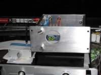
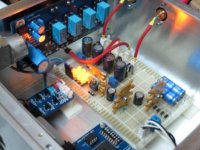
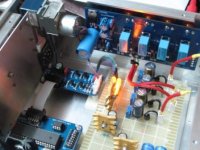
Looks amazing - what are all those bits inside?tHE iNSIDE.....
Alan
I recommend <2Hz for a power amplifier and another octave lower for all source components.if I use a 4.7uF cap with 10k resistor the cutoff corner freq is 3.2Hz. Does that sound right to you?
I might try hooking that up in series and see does it solve the problem
That would equate to >=160ms for the Lightspeed input.
a 500k or 1M or 2M pot will decrease the minimum LED current and thus raise the maximum resistance of the LDRs.Going back on what I said above...... the only thing that would be nice in addition to all this is to get a wider useable range on the lightspeed. I thought that upping the impedance of the pot would give me a bit of this.
i.e. raising the pot value increases the input impedance. At half rotation of a linear pot, a 2M pot will allow about 3uA (3V/1M=3uA) through to the pairs of LED strings.
This will give a higher range of volume adjustment as well as a higher input impedance.
- Home
- Source & Line
- Analog Line Level
- Lightspeed Attenuator a new passive preamp