Group Buy
I think if you guys get together and order from RS you will be very happy. My sorted LDR's are all over the place, both in slope and offset. There were matched at three current levels.
The exponetial slope needed for atttenuation makes matching much less critical than you might expect. I checked some stereo pots and was shocked at how poorly they tracked. Some were 50% at middle range, and these were expensive conductive plastic.
My recommendation is two use two control stereo pots, and not the trimmer circuit. This way a small imbalance is easily corrected. I use the two controls when chasing problems from all the diy and modified gear in my system. Sometimes there are lots of gremlins.
I keep wanting to add a buffer after the Lightspeed clone. Thinking of a simple jfet or BJT with degeneration. But am completely happy with the sound as it is.
George
There are a number of possible sources in Europe, of which Banzai is one. RS (UK) has the best price so far. But if no one in the UK is volunteering, there would be no group buy. As mentioned, I already got 25 SR3s from RS Germany, so I have no urgent need.
George put it very well, the advantage of the Group Buy is not only a bit of saving, but more importantly the better match.
Patrick
George put it very well, the advantage of the Group Buy is not only a bit of saving, but more importantly the better match.
Patrick
This seems to be an ideal way to do a multichannel attenuator with only a stereo pot. You just have to match as many LDRs as you have channels (not sure how hard that will be).
I really want to give this a try my my multiamped system. I already have a motorised remote controlled 100K pot. Is there a more clever way to do balanced channels then a shunt for each leg?
I really want to give this a try my my multiamped system. I already have a motorised remote controlled 100K pot. Is there a more clever way to do balanced channels then a shunt for each leg?
Is there a more clever way to do balanced channels then a shunt for each leg?
YES! Imagine a shunt regulator: a series resistor and a adjustable shunting resistor to ground. Now imagine two of those, one for + and one for -. Now, instead of connecting the shunt resistors to ground, connect both ends to each other, so that there is no connection to gnd anymore. Now you can change the two independent shunt resistors for one!
I know, I picture says a thousand words, but I don't have one on hand right now.
Erik
ErikdeBest said:
YES! Imagine a shunt regulator: a series resistor and a adjustable shunting resistor to ground. Now imagine two of those, one for + and one for -. Now, instead of connecting the shunt resistors to ground, connect both ends to each other, so that there is no connection to gnd anymore. Now you can change the two independent shunt resistors for one!
I know, I picture says a thousand words, but I don't have one on hand right now.
Erik
So if I understand you correctly you are putting a "T" between the legs? Voltage dividing between the two legs and then shunting that to ground. This would require 3 LDRs if I understand this correctly? One in series with each leg and one from the voltage dividing node to ground.
Hi JoshK
Here is a picture (post 10), worth a thousand from my confusing english words.
http://www.diyaudio.com/forums/showthread.php?s=&threadid=77664&highlight=
You see that you will need just one LDR per channel + 2 high precision resistors.
Erik
Here is a picture (post 10), worth a thousand from my confusing english words.
http://www.diyaudio.com/forums/showthread.php?s=&threadid=77664&highlight=
You see that you will need just one LDR per channel + 2 high precision resistors.
Erik
> Nelson Pass : I don't trust those figures, and I would have to run them myself for these parts, as I am unaware of any big advances in Cadmium Sulfide cells. My examples had large distortion at ordinary line levels.
According to information from both Silonex and Perkin Elmer, the amount of distortion depends greatly on material type as well as voltage rating / level. There are types from Silonex with much higher distortions.
But I have no data to support or disclaim the Silonex data. The LDRs are there, just no time to measure as yet. I am also not for or against LDRs, but I am most curious to find out.
Patrick
Here is a link to local preamp shootout including a lightspeed clone for those who might be interested http://www.dtvforum.info/index.php?showtopic=36129&st=80
I have no relationship with George, I only corresponded with him for the first time yesterday.
The Lightspeed clone was up against some very well regarded pres and did very well.
Cheers,
Paul
PS: Starts at about post 88
I have no relationship with George, I only corresponded with him for the first time yesterday.
The Lightspeed clone was up against some very well regarded pres and did very well.
Cheers,
Paul
PS: Starts at about post 88
Hi,
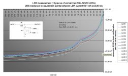
I have developed a µC circiut to digitaly control a current source and to measure the resistance of LDRs for matching purposes. See measurement details in the attached file. The Pot-Solution (100K log) to adjust the current of the LDR's is not very comfortablemm, because it is to sensitive. So I will do that at a later point with a µC including remote control and fixed steps for attenuation.
Conclusion of measurement: to match the LDR's 2 or 3 measurement points are enough, because the progression is always near the same. If you are comfortable with channel accuracy of arround 1-1,5 dB you only need a few LDR's to match them. For multichannel purposes or accuracy of 0.5 dB you have to measure much more pieces to find matching pairs.
Arne
Attachments
> I have developed a circiut to digitaly .....
I have done a similar measurement for 25 unsorted SR3s, using a triangular wave function generator through a BUF634 buffer to drive the LED in series with a 560R resistor. One channel of the digital scope was connected across the 560R resistor, to measure LED current, the other channel across the LDR itself, which is connected in series with a 10k Caddock MK132 to a 5V battery supply, to measure attenuation (voltage).
Results are similar to yours.
The good news is, the resistance goes down to about 60 ohm, as stated on the datasheet.
The bad news is, if you want 0.5dB match over a range of say 5k ohm to 100 ohm, we only managed to find 4 good pairs, no 3's, quad's, ...... So for a set of 5, I would recommend measuring at least 200 (Similar experience with MOSFETs).
The idea to use DAC of a microcontroller is also what we have in mind. So excellent idea Peufeu. I am useless with uPsoftware, so am most grateful if any of you would be kind enough to help. An Atmel Mega1280 only cost a few Euros, and would have all the functionalities one might want.
Patrick
@perufeu
To autocalibrate the LDR's at powerup would be easy to do, because of the eqaul progression it would be enough to measure at
a few current points
@EUVL
I agree with you that you have to measure a lot to have 0,5 dB pairs, but 200? I have purchased around 50 LDR's and
with old measurements method (Multimeter) I was able to find 3 sets of 4 matching LDRs (for series/shunt configuration).
Have to calculate the dB discrepancy with the automatic method again.
General you could use the LDR's in shunt configuration with a fixed series resistor, makes much things easier.
Meantime I have switched back to my stepped attenuator. In my opinion after several listening tests the fixed attenuator
is the better attenuator. With the LDR's I have a little lack in high frequency details and the low frequencies seems sofish. Perhaps
it is the impendance of the LDR attenuator, I have measured 18,9 K at listening level or this is due to the distortion of the LDRs. I tried that with 2 different amps, "Mauros LM3886 My RefC" and a fine class a amp.
As perufeu mentioned, to autocalibrate the LDR you need a relais in signal pass, but when you use the "bad" relais for calibrating or source select you could use a few more of then and build a complete attenuator with relais. That will also have abilities to remote control and you can realise a fixed imedance.
Because of the LDR sensitive in the low current range you need rocket science to adjust accurate in the higher resistance range to get a fixed output impendance (eg. 10 kOhm) at all listening levels. I will experiment with that, for multichannel the
LDRs make still makes sence, but for high end stereo in my opinion it is not worth to spend a lot of time and money with that.
The suggested Lightspeed solutiuon from Goerge is very good because of its simpleness and the good results.
Arne
> I agree with you that you have to measure a lot to have 0,5 dB pairs, but 200?
My experience with MOSFETS -- 25 pcs and you are lucky to get 2 sets of 4. 200 pcs I got 4 sets of 12, many sets of 8s & 6s. Only need to throw out 4 (out of 200) for regulators and what not.
LDRs are similar, in a way.
If you want say 2 sets of 5 matched to better than 0.5dB over range, I would not take less than 100. Of course you might well end up with many more 4s and 3s and 2s to offer here on the Forum.
Microprocessor is the best way out, in my opinion. You can match to 0dB, or resolution of your measurement equipment.
Auto-calibration is not as simple as it sounds, as the ADC in the uP limits your resolution at high attenuation. I personally would still stick to a high precision miltimeter.
> General you could use the LDR's in shunt configuration with a fixed series resistor, makes much things easier.
I have intended to do exactly that.
> I have measured 18,9 K at listening level.
!!!!!!!!!
I suppose if you do all passive, probably not surprising.
I only intend to use between 50 ohm to 2.5k ohm.
Patrick
> So for a set of 5, I would recommend measuring at least 200 (Similar experience with MOSFETs).
OK, so no way to avoid a microcontroller for multichannel then.
For multichannel (digital crossover project in my case), LDR is likely to be a lot cheaper (and smaller) than relays.
> the ADC in the uP limits your resolution at high attenuation
You need a cheap slow high resolution delta-sigma ADC and a cheap slow multichannel DAC which isn't delta sigma, so the cpu can switch itself off when not changing the volume, which would make less noise.
About the sound quality : have you tried with a high quality buffer after the LDR stage ?
> OK, so no way to avoid a microcontroller for multichannel then.
Well, for some uP idiots like me, it might be quicker to match 200 LDRs.
: )
> so the cpu can switch itself off when not changing the volume, which would make less noise.
No, that is not what I meant. To do autocalibration, I was thinking that you would send a number of discrete voltage from the uP out to drive the LED in the LDR (via a resistor), and then measure the resistances of the LDR in order to map the characteristic curve automatically by using the ADC of the uP. The problem is that while your attenuator wants to be a log device (say 0 to -50dB), the DACs and the ADCs of your uP is linear (say 8 bit). So at the low current or low resistances end, you have poor resolution, and hence low accuracy due to quantisation. A multimeter with autorange, on the other hand, would have little problem covering say 50 ohm to 5kohm with 4 digit resolution. But once you have mapped, you could store the transfer function in a look up map, and then you know how much voltage would would need to drive the LED (with serial resistance) to achieve what resistance at the LDR.
So you see why I said for some, it is easier to match 200.
But I am sure one of you guys can knock up some Atmel Assembler codes in no time. So I am awaiting with great interest.
: )
> About the sound quality : have you tried with a high quality buffer after the LDR stage ?
Not that far yet, but we never intend to use them purely passive. Either with a gain stage, or a complementary JFET follower, a la Curl. Or simply a BUF634 if you are lazy.
Patrick
uc's aren't that hard and you can program them in C using free open source gcc and the atmel IDE is also free.
I agree you need more than 8 bits precision which is why I suggested a cheap 16-bit sigma-delta type ADC.
You could also build the ADC in software using a comparator and counting the time it takes to charge a RC network. By wiring it in the right way you can linearize the log characteristic. It would be megacheap.
Autocalibration will compensate aging.
Also I don't like passive preamps because amplifiers like to have their input stages well balanced, which means the impedances on the + and - inputs should be equal, which is very difficult to do without buffering.
- Home
- Source & Line
- Analog Line Level
- Lightspeed Attenuator a new passive preamp