troystg said:I ordered the parts from Mouser today.
The IC part numbers are not the same from Farnell to Newark.
Searching Newark by description gives me three (3) choices.
http://www.newark.com/jsp/search/br...coder&Ntx=&suggestions=false&_requestid=72049
Suggestions?
For the HT12A try 97K1716, for the HT12D try 24M2761.
I'm becoming more convinced that the testing methodology and circuits used are not optimized. I bought 30 LDRs from Uriah. I tested them in groups of 10 at a time with my own testing rig. The first group had three good matches (under 5% difference across the full range), the second had four within 7% of each other and another two within a few percent, and the third had two sets of about 5% or better matching. My testing method can only test those 10 against each other, the results can't be compared reliably to the other groups of 10. My next version of a tester will be able to test 10 at a time to an absolute reference, allowing any LDR to be compared to any other.
I think the biggest problem is that everyone is using a fixed voltage and a resistor as a passive transconductance (voltage to current) converter. LEDs are current devices. A better solution would be an active transconductance converter to deliver a precise current to the LEDs. I'm working on a white paper and a few designs right now with this in it. It only adds a tiny bit of complexity and less than $1 worth of parts, plus will give the ability to go to lower volumes as well as adjust the rate of volume change to your liking. My wife just had our second child Tuesday, so I may not have much time this week to work on it, but I will get it done soon.
I think the biggest problem is that everyone is using a fixed voltage and a resistor as a passive transconductance (voltage to current) converter. LEDs are current devices. A better solution would be an active transconductance converter to deliver a precise current to the LEDs. I'm working on a white paper and a few designs right now with this in it. It only adds a tiny bit of complexity and less than $1 worth of parts, plus will give the ability to go to lower volumes as well as adjust the rate of volume change to your liking. My wife just had our second child Tuesday, so I may not have much time this week to work on it, but I will get it done soon.
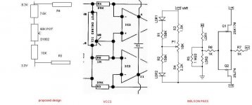
VCCS to simulate Nelson Pass's original design
Per latest VCCS design (post#2143), in order to simulate Nelson Pass's design (post# 1362) of 40db POT , should we add another two resistors in serial with the D1802 POT ?
Can anyone recommend the resistor to fit SR2 design since the design was based on SR3?
Maximus, I guess your 39K value for R1-R4 is calculated as 150k * 5V / (7.5V + 15V -3V).
Attachments
Fenris,
The cct as per post 1001 is a current control system - works like a charm - simply replace pot with 3, 4 or5 step switch and fixed resistors and without any further mods can do 2 at once.
If you have a controlled hotplate/heatsink/etc, (thermo switch) can clip devices to it for consistent temp control.
Suggest a look at how ZMs variation works too (the Poor Man's Serbian ....)
I agree that CCS can be a good thing. Many people are not used to using that circuit and frankly many dont understand it. My experience is that a very good number of the people that buy matched LDRs from me dont even get that the signal does not go through the pot. So for those that do understand or finally understand the circuit its easy for them to grasp how the whole thing works the way George has implemented it. I know for a fact that its the best sounding pot I have ever heard so I cant agree that CCS is "the way to go" but I would agree that its a great option. If you use LM334 you can get some serious milliamp resolution but are constrained to less than 10mA with the most basic circuit. Divide 5V by 500k. Can you get that kind of milliamp resolution on your CCS?
I recently got a batch I thought was bad. LDRs that is. I still am not convinced they are as good as I am hoping but it may come to pass. I just ordered 500k and 1MOhm trimmers to test with. Also got some 500k and 1MOhm dual audio pots. If this works out these will be the best LDRs I have seen as of yet. The tracking from preliminary and very quick testing looks awesome up to 250k then starts to waver around a bit, but not enough for me to think that matching out of 549 of them will be a tough thing. Time consuming.? YES. Tough? I think it will be easier and better than previous times. Cant wait for my Mouser order to get here.
Why am I jumping up to such serious Ohms? Because at 80k with 5VDC I get ~1k out of the LDR. No good. But with 200k I get 3k and with 500k I can get 9-11k. Thats pretty darn linear.
Uriah
udailey said:
Why am I jumping up to such serious Ohms? Because at 80k with 5VDC I get ~1k out of the LDR. No good. But with 200k I get 3k and with 500k I can get 9-11k. Thats pretty darn linear.
Uriah
I'm testing mine out to about 0.03 ma. I only measure current values for LEDs, not voltage. I'm getting about 15-20K reliably and with good matching. I'm going to try to run a few tests, time permitting this weekend and see if I can get a CCS to be stable, reliable, and repeatable down to 0.01ma or below. That should give a good usable range.
James - using a CCS applies not just for the actual circuit, but also for the matching as well. It's better to match under the conditions you'll use than under artificial ones. And the cct in post 1001 is just one way of skinning that cat. My way is different and some people may like it better. I'll just have to see how good I can make it first.
Fenris, can you tell me which date code is on your LDRs? Thats a very nice resistance to get. If they had a "jealous smiley" I would add that in. This one will do ")
So I am running with amps like .00001. 10microamps is as low as I can measure on my DMM but thats 5x more than the least amount of power I give the LEDs.
I think the deal here is that these are a different breed of LDR. Still the same Silonex ones we have all been using but something different, big time, about this batch.
Do you all know of a current source that can run single microamps up to tens of milliamps?
Uriah
udailey said:Fenris, can you tell me which date code is on your LDRs?
Uriah
About 50% are 109, 40% 159, and the rest 408.
Lightspeed remote control
Hi folks,
I have a batch of IR modules built now to go with the VCCS modules. I will be shipping these out during this next week. I should be able to get another batch of all the modules done next weekend to get the remaining outstanding orders completed.
Some of you have been trying to contact me this last week. I have been on holiday re-organising my workshop to cope with the increased level of business I have been getting since Christmas. Once I have finished the refurbishment I will get around to answering everyone as soon as I can.
Hi 2A3SET,
I chose 39K for the VCCS current range setting to roughly emulate the range Nelson Pass felt was optimal for the Silonex LDRs. It worked fine in my system so I left it in. My system is not a standard setup of equipment as there is no need for voltage gain in my line preamp or my power amps. If you want to operate the LDRs over a different range to match your system to your requirements, you can change the values of the current setting resistors. The LF 347 chip that drives the LDR LEDs should be good for up to 15ma of drive current without losing control. To stay within the LF347 output current range do not reduce the resistor value below 330R. You may have to reduce the value of R10 slightly to accomodate the additional load current. R2 and R4 control the shunt LDRs and R1 and R3 control the series LDRs.
For those looking for a current source for matching,
A current source to test LDRs for matching can be fabricated from an LM334 cascoded with an IXYS IXTP 02N50D to give higher voltage compliance so you can test 20 or more LDR LEDs in series. The current range can be set from 2 microamps to ten milliamps. This is enough to get a good match through the operating range. See the National Semiconductor LM334 application note for current setting information.
I have to say that I think the search for an absolute match is getting a little extreem. It really does not need to be that close to get good sonic results. For those that are going to use the VCCS module don't forget that the DS1802 has a balance control that tracks through the volume range once the channel balance is adjusted.
Regards
Paul
Ever felt like an idiot??
Today I do - in order to get more info on the VCCS and other things I have been reading through this thread, and then I came across something which could explain why I have slight balance problems on my Lightspeed - Uriah wrote 'you match the Series LDRs and then the Shunt LDRs'.
Penny drops - in the circuit you want the Series LDR's to match each other not the Series/Shunt. So I feel like a real idiot as I have put all my LDRs incorrectly into the boards for both the VCCS and the standard GeorgeHiFi Lightspeed i.e. a matched pair as Series/Shunt.

Thank goodness I have ordered two more sets from Uriah.
Time for a glass of wine.
Alan
Today I do - in order to get more info on the VCCS and other things I have been reading through this thread, and then I came across something which could explain why I have slight balance problems on my Lightspeed - Uriah wrote 'you match the Series LDRs and then the Shunt LDRs'.
Penny drops - in the circuit you want the Series LDR's to match each other not the Series/Shunt. So I feel like a real idiot as I have put all my LDRs incorrectly into the boards for both the VCCS and the standard GeorgeHiFi Lightspeed i.e. a matched pair as Series/Shunt.
Thank goodness I have ordered two more sets from Uriah.
Time for a glass of wine.
Alan
tinitus said:Ehh, why not simply swap them around
You have a series and shunt matched together, so the shunt should just be the matched series
But maybe not if its a technical matching issue
The problem is that by heating them up twice more means there is a good possibilty of messing up the matching - I think Georgehifi made a reference to ham-fisted solderers making a mess of things.
I prefer to leave them as they are - they sound excellent - I just have to adjust the balance when changing volume - hopefully with the remote controlled VCCS by Paul this will not be a problem.
Alan
No because the series are controlled by one pot and the shunt by another pot.... so this means that what happens to one channel happens to the other exactly the same. Never will you have channel tracking problem that is the fault of the carbon pot. If the LDRs are not behaving in a certain area then you will have to fine tune. Even with matching they can misbehave in areas where they have not been measured. For instance, say you measure at 4k, 20k, 40k and 80k.. Well if they misbehave at 60k then you will have to fine tune there.
Uriah
Uriah
Volume control in tube preamp
It's been awhile since I was on this thread, but returning here to the idea of an LDR volume control for my Atma MP-1 differential balanced integrated phono tube preamp. I changed phono section output tubes from 12AV7 to ECC99, which lowers output Z of phono to 2K. So I'm shooting for a balanced attenuator with minimum input Z of 25K. Reviewing my prior LDR test data, I see that a 5VDC supply with a 500K fixed resistor set LDR resistance around 25K. Am I right that a pair of 500K stereo pots would do it?
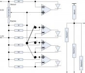
Also, I'm trying to understand the VCCS board, using two slaved PCBs for balanced. In this configuration does VCCS provide L/R balance control? Does VCCS have flexibility to raise input Z of attenuator into the 25K range?
Looking back over test data for 30 LDRs from earlier production, I'm fairly optimistic that I can get at least two sets of four to track within 5% up to 30K or 40K.
Thanks,
Dave
It's been awhile since I was on this thread, but returning here to the idea of an LDR volume control for my Atma MP-1 differential balanced integrated phono tube preamp. I changed phono section output tubes from 12AV7 to ECC99, which lowers output Z of phono to 2K. So I'm shooting for a balanced attenuator with minimum input Z of 25K. Reviewing my prior LDR test data, I see that a 5VDC supply with a 500K fixed resistor set LDR resistance around 25K. Am I right that a pair of 500K stereo pots would do it?
Also, I'm trying to understand the VCCS board, using two slaved PCBs for balanced. In this configuration does VCCS provide L/R balance control? Does VCCS have flexibility to raise input Z of attenuator into the 25K range?
Looking back over test data for 30 LDRs from earlier production, I'm fairly optimistic that I can get at least two sets of four to track within 5% up to 30K or 40K.
Thanks,
Dave
VCCS for tube preamp volume control
Having reread the whole thread I am dizzy, but questions for Maximus are:
1. Are there still VCCS and IR boards available?
2. Is your Application Note available for general study? I cannot find it on your web site.
3. For a balanced stereo attenuator with RC, do I need 2x VCCS, 2x IR receiver, and 1x IR transmitter?
4. Please outline in general terms the approach to raising input impedance of balanced VCCS to around 25K.
Thanks,
Dave
Re: VCCS for tube preamp volume control
post 2143, klick on pictures
Nice technology, but I will stay with udailey, dont like remotes
David Garretson said:Having reread the whole thread I am dizzy, but questions for Maximus are:
2. Is your Application Note available for general study? I cannot find it on your web site.
Dave
post 2143, klick on pictures
Nice technology, but I will stay with udailey, dont like remotes
- Home
- Source & Line
- Analog Line Level
- Lightspeed Attenuator a new passive preamp