How about using several 60W in parallell? I have some laying around, and thought about this but I was worried that a single bulb is not sufficient, ie it has to high resistance. By using say four in parallell , perhaps with individual switches this makes a versatile helpet. Much easier than usung the variac, which not always prevents magic smoke escaping. I have on a few ocassions turned down the voltage so fast it might have caused inductive kickback at the grid... ")
Don't be "worried" about the bulb wattage being too low.
The bulb is rated for mains use.
It will not blow up no matter how badly you wire up your equipment.
The worst that can happen to the bulb is that it reaches the end of it's life and fails. Plug in a new bulb.
I have mentioned a few times that having paralleled bulb sockets to allow adding extra bulbs would be useful.
The only danger is that you can "Start Up" with too high a wattage (or total wattage) and the current limit is set too high.
Start with a very low wattage and work your way up to a higher wattage.
A transformer alone, with no rectifier, can start up on a 15W candle bulb. It sometimes does not even flash.
With a rectifier and no capacitors it will probably start with the same wattage. I have not tried that, the smallest bulb I have is 25W and that will start all lone transformers and all transformers with a bridge rectifier.
25W will also start up a small to medium transformer with some smoothing capacitance.
A large transformer with a lot of smoothing capacitance may need a 40W bulb to start up and for the filament to dim down to a very dim glow. The capacitor leakage and rectifier leakage is what creates the glow. This should lessen to almost off over many hours as the capacitor re-form.
Last edited:
With the wonderfull EU. banning traditional bulbs we can now only get
"rugged duty bulbs" (the same thing with a different label!
Low energy (flourescent) and LED bulbs are obviously no good.
But what about the Halogen bulbs? what effect would using one of these have?
They claim 70 watt power consuption for the equivalent of 100 watt traditional.
Diall Bayonet Cap (B22D) 70W Halogen Eco GLS Light Bulb, Pack of 3 | Departments | DIY at B&Q
A halogen bulb is an incandescent filament bulb with a different gas inside the glass envelope.
The Filament is still tungsten. So operation in the Mains Bulb Tester is still the same.
The slight difference is the Halogen allows the filament to run slightly hotter for similar lifetime and thus the ratio of hot resistance to cold resistance is slightly higher.
The Filament is still tungsten. So operation in the Mains Bulb Tester is still the same.
The slight difference is the Halogen allows the filament to run slightly hotter for similar lifetime and thus the ratio of hot resistance to cold resistance is slightly higher.
Packrat behavior disclosed
Drat. So, the 40+ incandescents I've been hoarding for the DBT are taking up space for no good reason...150W and down. I've moved to greener bulbs throughout the house since the prices have become more reasonable.
The Filament is still tungsten. So operation in the Mains Bulb Tester is still the same.
Drat. So, the 40+ incandescents I've been hoarding for the DBT are taking up space for no good reason...150W and down. I've moved to greener bulbs throughout the house since the prices have become more reasonable.
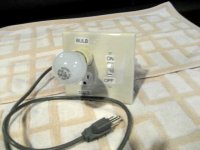
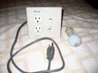
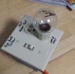
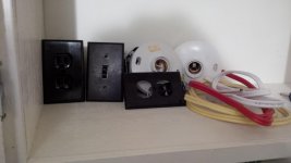
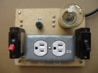
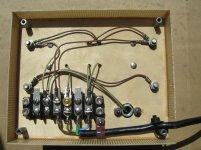
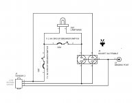
Here's mine; most parts were bought at a Home Depot store. I bought a plastic junction box, extra deep, for insulation/safety. There are no exposed conductors except for the AC mains receptacle. The photos show a 25W bulb; I bought several other wattages for testing purposes.
Before you ask: D.U.T. means Device Under Test. That's a new amplifier or other piece of DIY audio gear, which is being tested. Its AC mains plug goes into the DUT socket.
_
Before you ask: D.U.T. means Device Under Test. That's a new amplifier or other piece of DIY audio gear, which is being tested. Its AC mains plug goes into the DUT socket.
_
Attachments
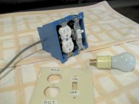
There are no exposed conductors except for the AC mains receptacle.
_
Mark-
That looks excellent!
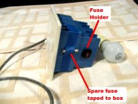
The bulb holder you found covers the bulb base well.
With the one(s) I bought, some bulbs had part of the metal base showing, so I added some tape to cover, after getting a bit of a 'buzz' one day.
Just a FYI for folks reading this.
Great little tool for the shop; every builder should have one. Keeps some of the excitement away!
Is that mains rated cable?
It looks more like low voltage cable.
Yes, it's part of the new electrical code in NL to use that color coded stuff. My uncle is an electrician, and this is some left over stuff we used to wire my dad's cottage.
Looks like audiophile grade speaker cable to me
Lol, it sounds "warm" and the bass transients are "deep".
- Home
- Amplifiers
- Power Supplies
- Light Bulb Tester