I did a little messing around in PSpice this afternoon, starting out with a current source loaded Schade cell using Darlingtons. If there is no buffer, the distortion into a 10k load is about 0.3% overwhelmingly 2nd & 3rd harmonic . For grins, I tried tacking on my usual p-chanel jfet buffer in front, with the results shown here. I was surpised by the drastic reduction in distortion with the buffer in place.
Edit - in practice, I would use parts in the TO-92L package for a little extra dissipation, as I'm running about 25-26ma of current in the output Darlingtons. The ones I have hanging around are the MPSW45 and a Fairchild TO-92L version of the MPSA63. This might make a nifty little lineamp if you don't mind the signal inversion.
wrenchone: In my schematics above, I assumed that the secondary winding of the transformer behaved like and/or mimicked the P-channel buffer in your schematics. Your simulations are useful and have already generated valuable data. Perhaps a headphone amp too.
Please examine the schematic of F5. I am seeing in it a Schade-style feedback. Here are my tentative observations of its elements:
- The F5 output stage is comprised of complementary MOSFETs with joined opposed Drains as the output node. This node is intrinsically a current source as compared with the joined opposed Sources node which is a voltage source [by convention]. The current source amp is is an important requirement for Schade.
- Unlike a classical Schade schematic, the front end of F5 is an inverting amp instead of a buffer; like the case of your schematic.
- Loop feedback is applied to the summing junction which is the node of the opposed Sources of the front end complementary JFETs. This bullet point and bullet #2 are an interesting modification to classic Schade feedback. It is a different approach ;but I hope with the same beneficial outcome.
- In the absence of loop feedback, this theoretically modified F5 [with its output at 0 VDC offset] defaults to a non-inverting current source amp.
Last edited:
wrenchone. A stereo amplifier of the preceeding schematic sounded great driving the MCM full range loudspeakers. Deep controlled bass and detailed highs from these brute drivers.
Please consider the attached schematic in your pursuit of the Elusive SIT. It has the elements needed to implement the methodology of Schade feedback. The output stage is like that of F5 [opposed drains of complementary MOSFETs], and it has the simple topology of diy F6. Rf and Ri will give a tunable handle on the optimal tilt of its characteristic curves.
I used half-shaded sine waves for positive-going signals, and half shaded triangle waves for negative-going signals; so as to track the correct signal phase through the circuit.
Brgds
Attachments
wrenchone: Mr. Pass called his "open loop" F6 of gain = 38 dB [x 79] a current source amp in the 6moons audio review. Loop feedback was applied to a novel summing junction which is the bottom primary winding of the Jensen transformer. The resultant closed loop voltage gain of F6 is 15 dB [or x 5.6]. The ideal name for this negative feedback needs to be Pass Feedback in favor of Black and/or Schade. Mr. Pass practices this style of feedback in "FET" circuits like Schade did in vacuum tube circuits. For example in ACA and F5 too.
There is high probability that the intrinsic pentode characteristic curves of the output JFETs in the open loop current source F6 amp were reorganized to triode-like characteristics after injecting Pass Feedback in voltage source F6 amp.
Brgds.
There is high probability that the intrinsic pentode characteristic curves of the output JFETs in the open loop current source F6 amp were reorganized to triode-like characteristics after injecting Pass Feedback in voltage source F6 amp.
Brgds.
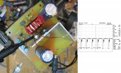
I've been working on a discrete buck switching regulator to act both as a voltage regulator and current limiter for the L'Fake Lite power supply. This will sit between two filter capacitors and take the rectified and filtered output of a 44VAC toroid (~62VDC) and turn it into 45VDC to run the L'Fake Lite, the object being to allow the AC to be snapped on without blowing the AC line fuses due to the current draw from the cold light bulbs. I'm using a discrete solution to be contrary (as usual), but also to avoid having to baby an IC. I'm about 70% of the way there. The attached picture shows my breadboard and a switching waveform. The remaining items on the plate are to increase the operating frequency (simple), and to reduce the dead time between switching cycles (the squiggly part of the attached waveform - we'll see). The converter was delivering 45V/2A with the heat sink barely warm, most of that dissipation probably due to the catch diode.
One could also do a pretty simple linear solution for this problem using a power darlington or mosfet, but that would blow a bunch of power, and the L'Fake Lite is hilariously inefficient as it is...
One could also do a pretty simple linear solution for this problem using a power darlington or mosfet, but that would blow a bunch of power, and the L'Fake Lite is hilariously inefficient as it is...
Attachments
I started off with doing a discrete borderline discontinuous buck converter (shown in the previous picture) for voltage/current regulation duty for L'Fake Lite to counter the nasty inrush current from the light bulb load seen at startup (it blows mains fuses - not nice). Nelson suggested unscrewing a couple of bulbs before hitting the "on" switch, but I want a more smoothly integrated solution than that, and after all, I am supposed to be an SMPS engineer in the glaring daylight hours, no matter what I do when I climb back into the coffin...
At any rate, the self-oscillating RCC solution has issues with repeatability, as well as relatively high levels of output ripple current and peak switch current, so I devised an alternate solution utilizing a discrete hysteretic buck regulator that has lower peak currents and ripple. I will post when ready, but my proto in its initial stages show 89% efficiency and lower ripple current. When I achieve more consistent operation, I'll let the cat out of the bag...
At any rate, the self-oscillating RCC solution has issues with repeatability, as well as relatively high levels of output ripple current and peak switch current, so I devised an alternate solution utilizing a discrete hysteretic buck regulator that has lower peak currents and ripple. I will post when ready, but my proto in its initial stages show 89% efficiency and lower ripple current. When I achieve more consistent operation, I'll let the cat out of the bag...

Self oscillating hysteretic buck gets tested again tomorrow. Hopefully new layout exorcises some lingering ghosties, now that I have other important issues sorted out. Once I am satisfied with overall performance, ultimate test will be to power up regulator using amp with all pernicious light bulbs in place to see if ultimate current limit chacacteristic of regulator works and keeps line fuse from blowing. I'll have to capture a power-up current profile to make sure things are really behaving.
I hope it works. You know and are skilled in this fascinating science.Self oscillating hysteretic buck gets tested again tomorrow. Hopefully new layout exorcises some lingering ghosties, now that I have other important issues sorted out. Once I am satisfied with overall performance, ultimate test will be to power up regulator using amp with all pernicious light bulbs in place to see if ultimate current limit chacacteristic of regulator works and keeps line fuse from blowing. I'll have to capture a power-up current profile to make sure things are really behaving.
Best regards.
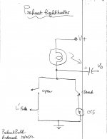
Hello wrenchone. A possible solution maybe to preheat the lightbulbs by lighting them at low intensity in a standby mode as shown in the attached diagram. The mechanical switches are ganged such that L'Fake is [Off] in the [On] Standby mode, and reverse. The CCS is intrinsically a hi Z load to L'Fake, and can be enabled continuously by deleting its switch.
Kind regards
Kind regards
Attachments
I'll work with a circuit like yours in Post #14. It will be a lower power device than you are using. I'll still use the byposs mode circuit for looks.That's one way - why don't you try it? I have other uses for the switching regulator (remember, it's also knocking down 64VDC to 45VDC), and I'll use the technology in other projects.
The voltage/current regulator is still a work in progress, but results are getting encouraging. Attached are the rise/fall times of the buck converter output voltage waveform. I may place a little bit of resistance (just a few ohms) in series with the gate of the switching fet to clean up the rising edge of the switching waveform.
Attachments
Attached is a picture of some of the operating waveforms for the regulator. The operating frequency is a little high - I want it to be around 60kHz at max load~4A. Shown here is the waveform at 2A load. The top waveform is the switching waveform at the input of the output inductor, and the bottom waveform is the output inductor, these two waveforms give one insight into operating frequency, duty cycle, programmed current hysteresis and the overall health of the converter. The circuit is designed around an LM393 dual comparator, a cheap readily available single-supply device that has the ability to sense near ground. A faster comparator with more output drive would be a good thing, and the LM311 is a possible candidate. I may need to add a negative rail to its supply voltage to make it behave. Efficiency is around 89%, including the losses in the toroidal transformer driving this regulator.
At any rate, I'll post a schematic when I'm satisfied.
At any rate, I'll post a schematic when I'm satisfied.
Attachments
Last edited:
wrenchoneThe ideal name for this negative feedback needs to be Pass Feedback in favor of Black and/or Schade.
I don't think this name would become popular outside of our little sandbox.
It is true, however, that there are several ways of achieving Schade effect.

Member
Joined 2009
Paid Member
... Papa swears that the resistively loaded solutions sound better than active loads.
what about reactive loads - does the use of a choke sound as good as using a resistor ?
Fortunately, our little sandbox is a worldwide stage due to the proliferation of diyAudio as a social-scientific medium. I hope that DIYers recognize, appreciate, and use the term Pass Feedback in their communications [I will]; because it has special performance attributes absent in generic NFB.I don't think this name would become popular outside of our little sandbox.
It is true, however, that there are several ways of achieving Schade effect.
Mr. Pass is a Physicist, and may view a lit incandescent lightbulb as a thermionic device. Electrons boil off the Wolfram wire, form a mobile sheath/cloud around it, and contribute to its classical solid state resistance. A hypothesis maybe that hot electrons may impart a "better" sound than cold ones meandering through a luke warm wirewound or Carbon composition power resistor.what about reactive loads - does the use of a choke sound as good as using a resistor ?
wrenchone: Consider replacing the power resistors in the source leg of the MOSFET with lightbulbs too. Go all the way. Hot electrons for cool sound! They maybe even hotter and sounding different by way of a lit Halogen lamp load. Rothacher's first generation SIT amp may have a totally different "thermionic" sound with a Halogen lamp instead of a Tungsten only load. It is a variable for study.
A string of 100 small clear light bulbs is used to decorate X-Mas trees. The bulbs are connected in series and operate directly from the power line. I pulled one off a spent string and energized it with a variable DC voltage. It glowed orange-yellow, drew ~60 mA with ~ 1V or less across it. Maybe, 2 such bulbs can be used in BA3 Front End replacing R10 and R11 = 22 Ohms. The capacitor C3 need to be non-polarized film should one bulb fail in operation. Thus, we will have a Light Burning Amp3 [LBA3] Front End. But; will this transformation make a great sounding amp sound even better?You know me, a sucker for incandescence.
Best regards.
Attached is a prelim schematic for the hysteretic buck converter I'll be using to power L'Fake Lite. It's based around a commonly available comparator (LM393). The converter sits on top of a ~60-65V rail and is biased with a floating winding that happens to be on the same toroid I'm using for the main power. A separate small transformer could also be used.
Floating the regualtor on the DC rail makes current sensing relatively easy, but makes drive a little problematic. The regulator could also sit at ground with the current sense in series with the return leg, but there are stilll issues. I also like to keep the return uncluttered. Let's just say that there are several ways of accomplishing this, none without issues. Drive transformers are out, as I want to operate pretty much up to 100% duty cycle.
Transistors Q3 and Q4 are used to speed up the drive. Q1 is the main switch, and was what I happened to have hanging around. There are some Infineon parts with much lower on resistance I might try when I get around to ordering some. Diode D1 is a 30A 100V Schottky. There are large bulk caps stationed before and after the regualtor.
Resistor R16 provides the comparator hysteresis that make this thing work. Gimmick C6 provides overdrive at the edges of the switching waveform. This goes a long way toward cleaning up the switching waveform. I suspect a ~2pF NPO disc would work as well, but a gimmick can be twisted together from some hookup wire in a jiffy (I used some wire wrap wire), and works just fine.
As this is still a work in process, expect a few changes. I'll probably do the ultimate start-up test tomorrow to test this circuit's ability as a current regulator, but right now, it functions just fine as a high power voltage regulator.
Attachments
Last edited:
- Status
- This old topic is closed. If you want to reopen this topic, contact a moderator using the "Report Post" button.
- Home
- Amplifiers
- Pass Labs
- L'Fake - A Cheap- A** Expedient to Replace the Elusive SIT