Im going to the shed right now and take a hammer to some PL519. Philips sold the machinery for the PL519 to EI, so i think it is a Philips cost cutting measure.
Edit, just checked, all the Philips examples have a classic cabonated grid (30) made out of hard metal. All the Telefunken examples (4) have grids aswell
Edit, just checked, all the Philips examples have a classic cabonated grid (30) made out of hard metal. All the Telefunken examples (4) have grids aswell
Last edited:
You should be able to tell the construction method without busting them.
If it was a Philips design, they may have heat treated the grid form stampings to remove internal stresses before winding the grid wire over them and assembling the tubes. (and re-stamped out or rejected any warps produced) One would think Philips would have thoroughly debugged a new design process.
Waiting for that to happen AFTER assembly and subsequent heating would be a problem, since the internal stresses from stamping would re-shape the stamping some, likely no longer flat. (Maybe the Philips procedure is not being followed correctly in current manufacture?)
Try sighting along the grid surfaces of the dissected tube to see if they are perfectly flat. And if the grid wires are still tensioned across the opening in the center. (same ringing frequency of all grid wires if stroked end to end with a straw)
In any case, trying some conventionally constructed tubes would be a good idea to see if the failure problem improves.
Last edited:
I had four that had no vacuum, i disassembled two and found the classic grid structure. The teles i have also have conventional grids. (Telefunken supplied machinery to EI as well)
I think that blasting the entire tube with a few KW of RF during evacuation will relieve some stresses from the metal.
Philips/mullard cut some corners from the 70's onwards, i know this from disasembling the same tube numbers from different lots, and some hearsay from ex-Philips employees.
I think the PL519 might best be used in a closed loop system, to get rid of the inherent unlinearity and parametric spread.
The RF getter activation process might well relieve the sheet metal bending stresses, but that's not the point in time you want to find out how it warped on stress relief. Plates probably don't matter that much, but accurate grid forms will. One can often find plates where the two ends don't line up real well where they are spot welded together. Hopefully the grids are better than that.
I think all the GU-50 tubes I got have gotten white getters now. Obviously big diameter pins are a hazard for vacuum.
I think all the GU-50 tubes I got have gotten white getters now. Obviously big diameter pins are a hazard for vacuum.
Last edited:
Even the Philips/telefunken examples have horrid tolerances. No real point in testing them on a parametric tube tester anyway.
They were made to switch (Or be used in closed loop systems such as regulated power supplies, in those applications tollerances don't really matter.
I tested a bounch some time ago at the supposed test data and they were easily +-60% wheras +-20% is common for most audio tubes.
I agree with you that the metal support is not the most elegant construction, however these will likely function fine in their intended role: Give the old TV some more life back in 1991. Their use in audio is a bit tricky, IMOH, better use a GU50 or something.
Sheet metal grid forms likely brought in a host of new issues to solve in production. I would imagine they pre-aligned the grid wires on such forms, so these merely had to be inserted into the mica insulators. No provision for pushing a grid up or down to align the wires after assembly. (bending a lead wire) Any in-accuracy resulting would have no second recourse with stamped grid forms.
This puts high accuracy requirements throughout the grid construction machinery, which didn't exist with the old "bend a lead wire" final grid alignment technique. Maybe slightly labor saving at final assembly, but this requires precision aligned and maintained grid machinery. Tubes are being made on -old- equipment, not too promising.
Grid mis-alignment will produce high grid 2 current, bad looking plate curves, and short tube life.
The spacing between a grid wire is the function of the accuracy of the machined gears, as long as you don't use those untill they are worn out, your spacing issues will likely be limited.
Appearantly some of the machinery from the EI factory escaped the scrapper, and is stored off site.
Appearantly some of the machinery from the EI factory escaped the scrapper, and is stored off site.
Its not gear wear that is the real problem, gears are digital ratio'd until they completely fail. Just an initial slack issue there.
The grid alignment problem is the wire winding "phase" match between the two grids. This is from lengthwise positioning of the two grids with respect to each other. This is normally solved by a small viewing window in the plate to see the mis-alignment, and the assembler bending a lead wire on one of the grids until they come into alignment. (so grid2 wires exactly behind grid1 wires)
This is possible with typical grid support rods that slide through the mica insulators (or ceramic insulators). However, stamped sheet metal or box grids cannot be slid lengthwise, they must be precision pre-aligned during construction before assembly.
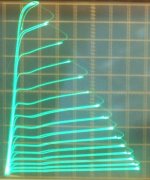
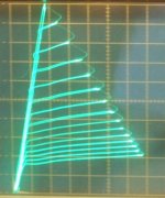
Here are some plate curves to illustrate what happens:
A) a well made (aligned) 17KV6A TV Sweep tube, 50mA/div Vert., 50 V/div Horiz., and 2 V steps on grid 1. (135V on grid 2)
B) a 30% mis-aligned 22KV6A, same 50 mA/.div. Vert., 50 V/div Horiz., and 2 V steps on grid 1. (135V on grid2)
Notice the reduced gm for B) and the increased minimum knee voltage. It is also drawing twice as much screen grid current.
I have another 36MC6 pair, one perfect and the other perfectly mis-aligned. The bad one draws so much grid2 current that its grid2 glows and it pulls down the grid2 V supply. Imminent failure likely. I keep that one on the shelf for interesting tests. It runs perfectly in triode mode however (although drawing a higher percentage of combined "plate" current through grid2 than a well aligned tube).
.
The grid alignment problem is the wire winding "phase" match between the two grids. This is from lengthwise positioning of the two grids with respect to each other. This is normally solved by a small viewing window in the plate to see the mis-alignment, and the assembler bending a lead wire on one of the grids until they come into alignment. (so grid2 wires exactly behind grid1 wires)
This is possible with typical grid support rods that slide through the mica insulators (or ceramic insulators). However, stamped sheet metal or box grids cannot be slid lengthwise, they must be precision pre-aligned during construction before assembly.
Here are some plate curves to illustrate what happens:
A) a well made (aligned) 17KV6A TV Sweep tube, 50mA/div Vert., 50 V/div Horiz., and 2 V steps on grid 1. (135V on grid 2)
B) a 30% mis-aligned 22KV6A, same 50 mA/.div. Vert., 50 V/div Horiz., and 2 V steps on grid 1. (135V on grid2)
Notice the reduced gm for B) and the increased minimum knee voltage. It is also drawing twice as much screen grid current.
I have another 36MC6 pair, one perfect and the other perfectly mis-aligned. The bad one draws so much grid2 current that its grid2 glows and it pulls down the grid2 V supply. Imminent failure likely. I keep that one on the shelf for interesting tests. It runs perfectly in triode mode however (although drawing a higher percentage of combined "plate" current through grid2 than a well aligned tube).
.
Attachments
Last edited:
Tubes are abused in that amplifier.
UL with 300 V B+ exceeds screen voltage rating.
Parallel tubes is another recipe for disaster due to possible current hogging and runaways.
Having a look at schematic would have been helpful in finding out if there are other abuses. Possibilities are too much resistance in g1 circuit and too high envelope temperature.
If I had an amplifier like this that regularly destroys tubes, I would consider reducing voltages, lowering power dissipation, and providing means for better cooling.
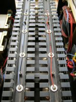
Looks like the grids are wound on sheet metal stampings. Never seen that before. (sensitivity to microphonics, mechanical jolts? Heat warping?) How accurate can they hold the thickness of the dents in the sheet metal, versus the diameter of conventional support rods (for spacing of grids)? (sheet metal stampings spring back some when released from the stamping press, not to mention distorting in shape and flatness some) There could be un-resolved issues in such a tube design. I would call that an immediate --RED FLAG--. Suggest trying another tube brand with real grid support RODs. Plus adding safety precautions to the amplifier design.
These tubes feature "frame grids" with the wires welded into the side profiles of the metal frames. One grid is made up of 2 frames that interlock - but this design feature does raise concerns.
Found this bit on Audio Asylum. Mirrors exactly what is discussed here.
Posted by TG (A) on September 9, 2003 at 20:55:25
In Reply to: EL509 / Sovtek 6PI45C posted by billanichols on September 9, 2003 at 19:42:55:
Yes, I've had the same thing happen. I bought a batch of 17 Svetlana 6pi45C valves about a year ago for my DIY T8 monoblocks and so far 4 valves have failed. 1 was DOA (grid short), 2 failed after a couple of hours use, 1 failed after a couple of weeks use and after the amps had been on for about 24 hours one day. In all failure cases (except the grid short) the getter flash was gone and when I examined the valves there was a crack across the base.
Infant mortality with these valves is apparently well known, and I was advised to expect 20-25% initial failure rate. I suspect that there is an inherent weakness in the design and/or manufacturing process which makes them susceptable to heat stress on the base of the valve.
I never noticed any audible signs of this approaching, either. They just suddenly fail, which backs up the idea that it's not an internal structure problem, but heat related - the glass cracks, gas gets in and the valve is useless.
To be fair, I've used the amps for about 2,000 hours since I built them and 6 of the original 8 valves I installed are still in there, sounding great and showing no signs of any problem. Seems like if the 6pi45C is going to fail at all it will be in the first few hours of use.
Cheers
Edit, just checked, all the Philips examples have a classic cabonated grid (30) made out of hard metal. All the Telefunken examples (4) have grids aswell
I also dissected an old broken TUNGSTRAM PL519 and it has the classic copper rod with a spiral would grid on both g1 and g2.
Must add that those old Tungstram tubes are solid and there are a lot of Steinhart amplifiers in the country still running on the originals.
But these new Sovtek 6Pi45c and related tubes are rubbish.
UL with 300 V B+ exceeds screen voltage rating.
Parallel tubes is another recipe for disaster due to possible current hogging and runaways.
Having a look at schematic would have been helpful in finding out if there are other abuses. Possibilities are too much resistance in g1 circuit and too high envelope temperature.
If I had an amplifier like this that regularly destroys tubes, I would consider reducing voltages, lowering power dissipation, and providing means for better cooling.
Yes I am going to wire the power section on Pentode mode and see how the amplifier behaves - ignoring the benefits of UL connection and the like (got 4 Manley Reference 600 amplifier also in and they are wired Pentode mode with the 6 pairs of KT90 tubes (KT90 concept derived from the PL519 I am sure and the reason they run them as Triode/Pentodes minding the G2 issue). KT90 tubes are also nightmares on their own and fail in the same manner as PL519s from my experience.
Cooling - tubes are sitting in free air and all the sockets are sinked on thick aluminium plate.
Plate voltage is already a low 300 vdc. But current draw is high.
An externally hosted image should be here but it was not working when we last tested it.
- ignoring the benefits of UL connection
There are hardly any benefits of UL compared to pentode connection.
Cooling - tubes are sitting in free air and all the sockets are sinked on thick aluminium plate.
This may not be enough. Free air flow should be provided around tubes through openings in the chassis. For this much total power of the amplifier, there should be fan-forced air cooling from under the chassis. I do not know the layout, but good design would provide at least 5 cm (2") distance between tubes. A stick-on temperature sensor on at least one of the tubes will give you an indication of overheating. It should be placed opposite plate's hot spot (middle of plate's cooling fin).
Also check the schematic for grid circuit resistance, which should not exceed 500 K PER TUBE. That is, if there are 4 parallel tubes, common Rg1 should not be more than 125 K. Data sheet also specifies minimum allowable g2 resistance. Each tube must be equipped with its own g2 resistor, not one common resistor for all screens.
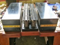
 The Fiery Inferno Amplifier
 Judging by the pictures here (near bottom of page):
Analogue Audio Engineering
This amplifier has to be over-heating grossly. All 8 output tubes, running class A, in a small box with shiny reflective sides everywhere except on top, where a wall of plate-cap heatsinks absorb the heat again. I do see ventilation holes around the tube bases, but this thing needs a blower to stay cool in there. Even the steel frame is rusting out from over temping. And are those exposed metal/plate caps on top? A death trap too.
Some serious re-work needed on those things I think.
Last edited:
There are many idiots out there who learned how to solder two wires and how to cut the 1" holes in a chassis hence became the Gods of Hi-Fi electronics design.
. . .
Some serious re-work needed on those things I think.
I see them placing the electrolytic caps over the hot tubes, mounting the tubes horizontally without aligning the grids vertically, or like this squeezing output tubes into such cases etc etc etc. What I do not get most: why they situate the ugly-cheapo-no-name caps protruding out of chassis like tubes, and hell, some are red-colored! Apparently, that means "The Performance" ))
To me, the first sign of "design" is zero screws on amp's top surface, only then I look further. Otherwise just another pity home-brew amateur's . .. craft ))
It looks like the metal "heatsinks" up top are just decorative (teflon insulators on caps), used to hide the plate cap wiring (which is insulated, for the most part, but can still see the bare connections through the cover strip gaps). But now this decorative but useless "heatsink" up top is just restricting air flow.
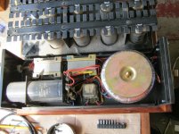
On the bright side, looks like the amplifier is in 3 parts, so could be separated for some cooling by lengthening some wiring and putting the tube section up top (stacked).
More pics from here:
Steinhart Bolero Monoblocks in for service
On the bright side, looks like the amplifier is in 3 parts, so could be separated for some cooling by lengthening some wiring and putting the tube section up top (stacked).
More pics from here:
Steinhart Bolero Monoblocks in for service
Attachments
Last edited:
It looks like the metal "heatsinks" up top are just decorative (teflon insulators on caps), used to hide the plate cap wiring (which is insulated, for the most part, but can still see the bare connections through the cover strip gaps). But now this decorative but useless "heatsink" up top is just restricting air flow.
On the bright side, looks like the amplifier is in 3 parts, so could be separated for some cooling by lengthening some wiring and putting the tube section up top (stacked).
More pics from here:
Steinhart Bolero Monoblocks in for service
Yes, those "heat sink" devices are for decoration only. They are not well thought out and not well made either. But man they sound good when they work.
- Status
- This old topic is closed. If you want to reopen this topic, contact a moderator using the "Report Post" button.
- Home
- Amplifiers
- Tubes / Valves
- Lets talk about the PL519