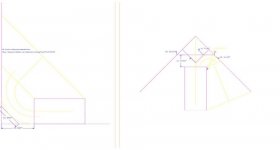
2 recommended corner loading schemes for labhorns - recommended 2 units, stacked (floor to ceiling) or 1 unit with a 'flare extention' to limit vertical expansion into the corner.
Borrowed from a thread on prosound web that I couldn't find to link to right now.
http://srforums.prosoundweb.com/index.php/f/3/0
Rob.
I'm doing the one on the left in a week or so...
Borrowed from a thread on prosound web that I couldn't find to link to right now.
http://srforums.prosoundweb.com/index.php/f/3/0
Rob.
I'm doing the one on the left in a week or so...
Attachments
Hi Jan
Will be using 2 in my room (21' x 10') 2 cabs are complete, just waiting for the arrival of the machine screws to bolt the drivers in. Have the amp and xo waiting - even got all the leads made up.... Hope to get them in next week. (After the weekend - have other stuff to do)
cheers,
Rob.
Will be using 2 in my room (21' x 10') 2 cabs are complete, just waiting for the arrival of the machine screws to bolt the drivers in. Have the amp and xo waiting - even got all the leads made up.... Hope to get them in next week. (After the weekend - have other stuff to do)
cheers,
Rob.
slowmotion said:That'll be fun, I'm sure.
Bet you can hardly wait
cheers
I am looking forwards to hearing them ...
I'd finished the cabs about 3 weeks ago, but the aluminium access panels took a while to make..More on topic, I'd love to see a 'horn speaker cookbook' for newbies like me. - I'm sure theres enough great brains on this forum to produce a great book between them.. and I'm sure it would sell well too.. I'd buy one anyhow..
Cheers,
Rob
I've made a kickstart for using Hornresp, if you like I can add it here, it basically tells you what every entry means.I've made a very sketchy start to a wiki on Horn Response, which I've used quite a few times, but have to confess I don't yet know exactly what every entry means.
http://www.speakerplans.com/forum/forum_posts.asp?TID=1314&KW=guide (after the WinISD Pro guide).
Wkr Johan
In the wiki, I found the following statement :
Is that really true? My understanding is that the compression chamber in front of the driver, coupling it to the front loaded horn, should be sized to roll off the SPL response at a prescribed frequency. The closed box behind the driver is what provides additional stiffness to reduce and control driver displacement and at the same time raise system Q (this is why low Qts drivers are prefered). The load on the front of the driver would seem to be primarily an acoustic resistive load. I don't see pressure equalization from this set-up, I only see some acoustic damping applied to the front of the driver cone. Am I missing something?
The compression chamber in a FLH equalises the pressure on both sides of the driver, in effect forcing it to operate in a more linear fashion. Hence distortion is further reduced in a FLH.
Is that really true? My understanding is that the compression chamber in front of the driver, coupling it to the front loaded horn, should be sized to roll off the SPL response at a prescribed frequency. The closed box behind the driver is what provides additional stiffness to reduce and control driver displacement and at the same time raise system Q (this is why low Qts drivers are prefered). The load on the front of the driver would seem to be primarily an acoustic resistive load. I don't see pressure equalization from this set-up, I only see some acoustic damping applied to the front of the driver cone. Am I missing something?
The compression chamber on a FLH actually causes non-linearity. As the cone moves, the volume of air in the chamber changes. It's probably not a big deal at home listening levels, though.
I don't know if the 'purpose' of a front chamber is to roll off the highs, but that is what it does. In an electro-acoustic analogy, it is an acoustic capacitance in parallel with the impedance provided by the horn, so it is shorting high frequencies to ground, preventing them from going down the horn while low frequencies pass right through. I think a compression chamber typically exists because there is always some volume between the driver diaphragm and the throat of the horn when the throat of the horn is smaller than the diaphragm's area. This is especially obvious when you look at a high frequency compression driver with a phase plug.
Btw, going back to comments made earlier on page 1 of this thread, a typical front loaded horn will never revert to the typical DIY audio definition of a transmission line due to the sealed rear chamber. There is some range where the system moves from being a horn to being a driven resonant pipe, though. If you tune the resonant pipe system right, you can get good output from it, but probably not quite as nice as a horn.
Greets!
?? Properly sized, the rear chamber is applying acoustic damping proportionately to the rear of the diaphragm to keep its excursion linear, so why is this not pressure EQ? IOW, ideally you want the rear chamber Q to match the front chamber/throat's Q. It's this imbalance that makes getting optimal wide BW performance out of a BLH mostly wishful thinking.
GM
Johan, that's great!
I'm very happy to have someone who has already done some of the work, rather than have to enquire about it all! I expect I'll be incorporating that post shortly. Thanks.
Martin,
That quote I wrote based on my understanding of a post some time ago (possibly even in a search on horns) by GM.
I'm glad to see some experienced horn guys chiming in. I'm really just the horn newby hunting through posts and the net, trying to make sense of it all and to compile and distill it into a form useful to diyaudio members. IOW I need the input of you guys to make sure I get it right.
John, regarding chambers I'm not sure we are all talking about the same thing. By compression chamber in a FLH, I'm talking about the sealed box enclosing the rear of the driver with its magnet and basket. Were you talking about a compresssion chamber in between the front of the driver and the throat? Does this have a special name?
I'm going to have to see if I can put together some graphics on this wiki. It's hard to get far on some topics with just text!
Rob, I'm keen as I'm sure many others are, to hear about your Lab subs. IIRC, a simulation on John Sheerin's site showed a corner placement similar to one of those which extended the F3 from 40 Hz down to the mid 20s. I'd imagine in some solidly built rooms that you could get down to 20 quite easily without eq and no need for a sub below.
Hi all
Unless if using compression drivers down low, maybe.
Compromises, compromises.....
Yes, but as you know you can also tune the compression chamber to widen the usable bandwith of the horn uppwards a little bit , if needed. Smaller chamber - sharper knee.
But that would make the non-linearity more of a problem I'd guess...
cheers
PS:
By the way John, thanks for posting your simulations of waves around bends in WE15A like horns on you webpage. Very interesting!
John Sheerin said:The compression chamber on a FLH actually causes non-linearity. As the cone moves, the volume of air in the chamber changes. It's probably not a big deal at home listening levels, though.
Unless if using compression drivers down low, maybe.
Compromises, compromises.....
I don't know if the 'purpose' of a front chamber is to roll off the highs, but that is what it does. In an electro-acoustic analogy, it is an acoustic capacitance in parallel with the impedance provided by the horn, so it is shorting high frequencies to ground, preventing them from going down the horn while low frequencies pass right through. I think a compression chamber typically exists because there is always some volume between the driver diaphragm and the throat of the horn when the throat of the horn is smaller than the diaphragm's area. This is especially obvious when you look at a high frequency compression driver with a phase plug.
Yes, but as you know you can also tune the compression chamber to widen the usable bandwith of the horn uppwards a little bit , if needed. Smaller chamber - sharper knee.
But that would make the non-linearity more of a problem I'd guess...
cheers
PS:
By the way John, thanks for posting your simulations of waves around bends in WE15A like horns on you webpage. Very interesting!
I've now added Johan's info into the Horn response help guide, but still looking for some info on a few terms (see wiki):
http://www.diyaudio.com/wiki/index.php?page=Horn+Response+Help
If you have an answer you may as well just add on to the wiki
http://www.diyaudio.com/wiki/index.php?page=Horn+Response+Help
If you have an answer you may as well just add on to the wiki
Hi Paul,
I was talking more about bits and pieces I've read on the forums. Basically I just went to each of the speaker forums and did a search on 'basshorn' and 'midhorn' etc and read all the results. All the websites to do with horns in my favourites folder are already known I think:
http://www.volvotreter.de/index.htm
http://www.speakerplans.com/
http://www.audioroundtable.com/PiSpeakers/messages/14408.html
http://www.prosoundweb.com/lsp/
http://www.diyaudio.com/forums/showthread.php?s=&threadid=16616&perpage=10&pagenumber=3
http://diy.cowanaudio.com/index.html
http://roborg.freefronthost.com/infra-horn.htm
http://db.audioasylum.com/cgi/searc...wmessage=&sort=score&sortOrder=DESC&forum=hug
http://www.speakerstore.nl/index.php?l=en&pg=11&p=&c=23
http://www.positive-feedback.com/Issue4/edgarinterview.htm
"John, regarding chambers I'm not sure we are all talking about the same thing. By compression chamber in a FLH, I'm talking about the sealed box enclosing the rear of the driver with its magnet and basket. Were you talking about a compresssion chamber in between the front of the driver and the throat? Does this have a special name?"
----------------------------------------
Paul,
IMHO, the term "compression chamber" always applies to the area between the driver and horn's throat.
The sealed box enclosing the driver's magnet & basket serves the purpose of a baffle just like in any ported or sealed enclosure.
In a BLH for example, the comprsn. chamber lies at the back of the driver, the driver's front radiates free to air.
Similarly, for a FLH, I feel one could also leave the driver's back exposed like in an open baffle setup.
Regards,
Francis
- Status
- This old topic is closed. If you want to reopen this topic, contact a moderator using the "Report Post" button.
- Home
- Loudspeakers
- Multi-Way
- Let's get horny! (aka building a horn design resource)