
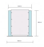
 480mm!!!
Yes. It's wide. At first, I was thinking about 430mm, which is the same as the body width, but changed mind to 480mm to have 25mm wings to the left and right.
The final dimensions might be slightly modified. It would depend on the heat sink dimensions that I will order tomorrow.
I am going to have upper CCSs using N- MOSFET . . .
But, using P- could be better . . . ? More quieter . . . ?
Hmmmmmm . . . . . .
In a dilemma . . .
Regards
jH
The final dimensions might be slightly modified. It would depend on the heat sink dimensions that I will order tomorrow.
I am going to have upper CCSs using N- MOSFET . . .
But, using P- could be better . . . ? More quieter . . . ?
Hmmmmmm . . . . . .
In a dilemma . . .
Regards
jH
Just what I thought! That geometry wouldn't please my eyesKind of big front JH, 480mm!!!
 Seems like the chassis would be 480x480! Not a nice sight to me, sorry JH
Steen.
jh6you said:If I use 0R22 source resistors, is the inner voltage gain of F1 could be approximated as about 25dB with 8ohm spker? I want to roughly figure out the input impedances for mine.
The gain of an F1 is about 13.9 dB. The F2 is about 15.6 dB.

Failed to get IRF240 . . .
IRF150 and 250 only available here . . .
Both IRF150 and 250 have high input bypass pF, compared with IRF240. IRF150 about 2.5 times while IRF250 about 2 times higher. So, If IRF240 gives me fc at 100kH, IRF250 would give me fc at 50kHz. Will it be a great concern if the amp should live with fc at 50kHz?
Estimated based on C in(Miller) = Cgs + Cds x (1+A)
Regards
jH
Thanks a lot, JH. I will take that as a complimentLadies and gentlemen! . . . Steenoe is my wife . . .
Still, an even sided square s*cks, somehow

Steen
BTW.
Sorry to say so, but so did I! I did try to connect to a cheap source for those, on your account, But they havent got any, anyway's!!Failed to get IRF240 .

Tanks to Nelson, i with confidence bought IRFP250 . . .
The heat sink shop did not wait for me with the size i wished . . .
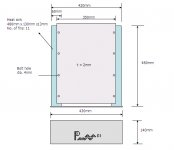
I re-ordered the size of 480x130x6 having 11 fins . . .
The size was by eye measure . . . not by calculation . . .
Feel somewhat smaller . . . Anyhow . . .
The attached drawing is the final dimension of the chassis . . .
Hope this time steenoe will say ok . . .
Then, I will sign the divoce paper . . .
Nelson
From now on I'd like to call you Nelson . . . Do you mind . . . ?
My F1 circuit is based on your Zen V7.
For the two current sources, I have thought to use p-channel mosfet. But, simply to use one IRF250 for all, I go with n-channel.
The current sink is exactly same as the one of Zen V7.
By the way, as shown in my concept drawing Rev.2 above, I have Rgs (instead of the R going to the ground in Zen V7). I have this Rgs for two things. One is for DC control, and another is to let it stay there as a form of boostrapping.
Could you let me know whether "the form of bootstrapping" will do its function? If so, I might understand the circuit much better.
I have lack self-confidence as I am not an electrician . . .
Regards
jH
Attachments
jh6you said:From now on I'd like to call you Nelson . . . Do you mind . . . ?
By the way, as shown in my concept drawing Rev.2 above, I have Rgs (instead of the R going to the ground in Zen V7). I have this Rgs for two things. One is for DC control, and another is to let it stay there as a form of boostrapping.
Could you let me know whether "the form of bootstrapping" will do its function? If so, I might understand the circuit much better.
I have lack self-confidence as I am not an electrician . . .
1) No, I don't mind. Everybody else does, if I'm lucky.
2) If it works, fine. I do it a little differently, looking for greater
stability of voltage across the bottom current source, as you
will see in the upcoming service manual.
3) Very few electricians as defined in the U.S. have much
understanding of electronics - they specialize in routing power
off the AC power lines.
Nelson Pass said:
2) If it works, fine. I do it a little differently, looking for greater
stability of voltage across the bottom current source...
Like the one's feeding the input stage of the A75, by any chance?
Hi jH !
I suggest that you find another way of biassing your gates. The resistors from gates to sources will give voltage-feedback, which will lower both the input and output impedance. It will turn the amp into a voltage amplifier, which was not what you wanted ?
Maybe you could just use a voltage divider from supply to ground and bypass the lower resistor with a cap. Then just put 47 KOhm from there to the gate. Then you wont need the series resistor.
Or you can use a dual supply and just tie the gates to ground.
I`m looking forward to hearing about your listening impressions.
Thorsten
Indeed, he doesHope this time steenoe will say ok . . .
That chassis looks very pleasing I just hope you can still fit the trafo's in there Steen
steenoe
I signed the paper.
my trafo is 12-0 12-0 400VA.
The dimension is 130mmx130mmx8omm.
Two of them will walk side by side into the inner space . . .
I misprinted. The size of heat sink is 480mmx130mmx60mm.
Thorsten
I 80% understand what you are talking about. Thanks!
If it is turned out as a voltage amplifier, it would be still not bad.
If so, I could test it on my current speaker . . .
Actually, I like to do exploring . . . learning . . .
Later, I could switch the circuit into the original Nelson's F1 . . .
And, would test it on my new single drive spk . . .
Nelson
It is somewhat difficult for me to interprete "If it works,".
Best Regards
jH
jh6you said:It is somewhat difficult for me to interprete "If it works,".
Well, the bias point on the Drains is either stable, or it wanders
around. If it's stable, then it works.
Eah . . . I couldn't sleep well for days, being afraid of the potential instable offsets . . . even if I put the source resistors below the gain mosfets . . . dreaming of a possible stability.
My head is chaos . . . with the electron traversing all of time and space . . . totally . . . out of control . . .
Still I can't open the firstwatt web site . . .
Regards
jH
My head is chaos . . . with the electron traversing all of time and space . . . totally . . . out of control . . .
Still I can't open the firstwatt web site . . .
Regards
jH
Resistors below the Sources alone will not give you sufficient stability. Your worst case scenario is that one output's DC offset drifts upwards while the other drifts down. The resulting DC will flow through your voice coil, leading to unpleasant results.
Ideas for you to play with:
--The simplest solution is to cap couple the outputs. It's reliable, easy, and guaranteed to stop the DC. The downside is that the caps will have some effect on the sound quality. They'll have to be fairly high capacitance, which means electrolytics--although you could easily bypass them with film caps to help things out. Needless to say, this isn't what Nelson did on the F1, but it's quick and easy and you'll be able to sleep at night knowing that you won't roast your driver.
--Take a look at the upper "load" current sources. (Assuming that the gain devices are well matched, any variation in the current feeding the differential itself will be common mode, and can basically be ignored...unless it gets so far off that you start getting asymmetrical clipping.) They're going to drift with temperature. First, you make them as thermally stable as possible, meaning lots of thermal mass. Then you create a feedback loop to monitor and correct the current regardless of temperature.
--Create a feedback loop that corrects the DC offset as compared to ground.
--Create a feedback loop that monitors the DC offset of the other side and sets out to match that (not some arbitrary DC voltage from ground).
--Use resistors to bridge from each output to create a sort of virtual ground mid-way between the two output nodes. Use that as the basis for comparison.
I'm just quoting from memory. I made a list of things and played with some of the most promising candidates. There are probably some that I'm forgetting.
Just a few ideas for amusement.
Grey
- Status
- This old topic is closed. If you want to reopen this topic, contact a moderator using the "Report Post" button.
- Home
- Amplifiers
- Pass Labs
- Let me lite fire - Nelson Pass F1