suggestion
Try to give audio signal directly after the pre amp stage to the right pin of C20 & C21 as mentioned here : http://www.diyaudio.com/forums/class-d/90500-lepai-t-amp-ta2020-98.html by using a 2.2uf capacitor in series. This way you can see if the Lepai works as a power amp. If it works then the pre stage op amps are dead. Opamps die easily if short circuit their output.
Try to give audio signal directly after the pre amp stage to the right pin of C20 & C21 as mentioned here : http://www.diyaudio.com/forums/class-d/90500-lepai-t-amp-ta2020-98.html by using a 2.2uf capacitor in series. This way you can see if the Lepai works as a power amp. If it works then the pre stage op amps are dead. Opamps die easily if short circuit their output.
Recently I fixed new ta2020 chip board & it looks fine.. no dimming blue led this time.. But when i input the audio signal to it, nothing seems to be coming from amp audio out.. I'm really disappointed about this as i already ordered a extra IC and waited for so long to receive it..I really appreciate your help in this case..
What are the things to check ?
Thanks
Got my Lepai!
It's in the truck just waiting on me... Here are some answers to my (own) questions.
Power Supply - So I found a old laptop brick that was 20v 3.5 amps. Normally this would be waay too much power, but I have a power inverter installed in the truck, and was thinking that the inverter would limit the power to 12V, boy was I wrong in thinking that... duh. It has low/high voltage/amps protection, but it does not limit it to 12V. Well, I got the multimeter out and was getting right at 19v on the old laptop brick plugged into the inverter. It would only show the voltage for about a second or two, then drop to nothing. I think the protection circuit was kicking in during this multimeter test. So I did good here by checking and not assuming...
So... this left me with three options.
1) use the old 20v brick with a step down regulator/diode. Not good, waste lot of energy
2) goto the local RS hobbyshop and buy one there - OK, but WAY expensive (25$+)
3) look for a used 12v unit. Found one for 5$ at local computer repair store. It is 12v and 3 amps. perfect.
So now I just go to test it and try out the unit. I am going to try plugging into wall first, test voltage with multimeter, ect...
Here are a couple questions for you guys:
If I am using this 12v brick plugged into my power inverter in the truck, will it allow the initial cranking voltage to be more than 12v? Won't the 12v supply be limited to just that 12v (or maybe a little more or less but not above 14v)? I'm asking because another poster has tried this in auto application, but seemed to have trouble due to the cranking voltage being 14v. I'm not sure what power supply he was using though (seems like it might have been wired direclty to the battery or maybe fusebox). I just want to make sure I don't fry this unit.
How can I FOR SURE test this new brick to make sure the + and - leads in the connector are correct for the amp? I seem to remember somebody frying theirs because these were switched.
Assuming there is no smoke or cuss words, will report back soon. Hopefully follow up with some basic cap/inductor/led fault light mods...
Thanks to all! This is the most fun cmas gift (to myself) I got this year, even if it is cheap and chineese.
installed and working in car with power inverter.
It all works....
Not as loud as my old pioneer head unit (35wx4 - display was faded - mfg in 1998), but works pretty well. Easy to hook up. Much less wires to mess with in the dash since the PS is ran to the inverter. I only had to find/snip the speaker wires from the old unit/under the dash.
I did run into a funny little snag. I had no input to input cable to go from MP3 player to the amp. I have plenty of speaker wire and old pair of non functioning headphones, so I went got some RCA jacks and tried to make an input to RCA cable (failed miserably). I was being cheap and skipped the $10 cable and after my homemade version did not work, I ponied up $15 for a 6' input to input jack. Worked like a charm.
Follow up questions:
Up next:
It all works....
Not as loud as my old pioneer head unit (35wx4 - display was faded - mfg in 1998), but works pretty well. Easy to hook up. Much less wires to mess with in the dash since the PS is ran to the inverter. I only had to find/snip the speaker wires from the old unit/under the dash.
I did run into a funny little snag. I had no input to input cable to go from MP3 player to the amp. I have plenty of speaker wire and old pair of non functioning headphones, so I went got some RCA jacks and tried to make an input to RCA cable (failed miserably). I was being cheap and skipped the $10 cable and after my homemade version did not work, I ponied up $15 for a 6' input to input jack. Worked like a charm.
Follow up questions:
- If I find a 13 or 14v PS, what amperage should I look for (3-5?). How much louder will this make the amp?
- Should I even try scavenging parts from the old pioneer head unit (caps/PS/regulator)? It is big and HEAVY compared to the Lepai.
- I noticed some in line fuses on the wires to the old head unit. Should I add in any fuses ect. for protection? I have the PS plugged to the inverter, and the inverter straight to the battery terminals.
Up next:
- Clean up wiring
- fault LED
- op amp bypass - should make it a bit louder and I have equalizer on MP3 player anyway...
- inductors and caps
- mount in dash
!
I would suggest not to go more than 13v. Keep in mind that this is a low quality Chinese amp & maybe poor children build it under an adults' supervision. Many components are "no name" end even used ones, at least the tripath chip inside is ok. I think "the how loud it can go issue" is a matter of how much current the amp can take (not voltage). Mine tested in max volume (till speaker started distortion from amp clipping) with an ampere-meter , draws about 1.8A (this is as far this amp can go : 2X20watt for a 4ohm load). I use a 6A/12v power supply which is enough. Bypassing the opamp stage & making this a small power-amp will make huge improvement, in fact the Lepai transforms into a much much better amp.
I would suggest not to go more than 13v. Keep in mind that this is a low quality Chinese amp & maybe poor children build it under an adults' supervision. Many components are "no name" end even used ones, at least the tripath chip inside is ok. I think "the how loud it can go issue" is a matter of how much current the amp can take (not voltage). Mine tested in max volume (till speaker started distortion from amp clipping) with an ampere-meter , draws about 1.8A (this is as far this amp can go : 2X20watt for a 4ohm load). I use a 6A/12v power supply which is enough. Bypassing the opamp stage & making this a small power-amp will make huge improvement, in fact the Lepai transforms into a much much better amp.
It all works....
Not as loud as my old pioneer head unit (35wx4 - display was faded - mfg in 1998), but works pretty well. Easy to hook up. Much less wires to mess with in the dash since the PS is ran to the inverter. I only had to find/snip the speaker wires from the old unit/under the dash.
I did run into a funny little snag. I had no input to input cable to go from MP3 player to the amp. I have plenty of speaker wire and old pair of non functioning headphones, so I went got some RCA jacks and tried to make an input to RCA cable (failed miserably). I was being cheap and skipped the $10 cable and after my homemade version did not work, I ponied up $15 for a 6' input to input jack. Worked like a charm.
Follow up questions:
- If I find a 13 or 14v PS, what amperage should I look for (3-5?). How much louder will this make the amp?
- Should I even try scavenging parts from the old pioneer head unit (caps/PS/regulator)? It is big and HEAVY compared to the Lepai.
- I noticed some in line fuses on the wires to the old head unit. Should I add in any fuses ect. for protection? I have the PS plugged to the inverter, and the inverter straight to the battery terminals.
Up next:
- Clean up wiring
- fault LED
- op amp bypass - should make it a bit louder and I have equalizer on MP3 player anyway...
- inductors and caps
- mount in dash
Try to give audio signal directly after the pre amp stage to the right pin of C20 & C21 as mentioned here : http://www.diyaudio.com/forums/class-d/90500-lepai-t-amp-ta2020-98.html by using a 2.2uf capacitor in series. This way you can see if the Lepai works as a power amp. If it works then the pre stage op amps are dead. Opamps die easily if short circuit their output.
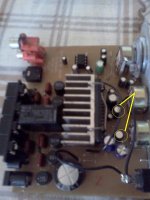
Thanks you very much for your reply.. However I'm unable to find c20 , c21 inside this board..attached below are the pictures of the board..please help me to find those 2 capacitors..could you please elaborate more about this procedure (more detail).. Thank you
An externally hosted image should be here but it was not working when we last tested it.
An externally hosted image should be here but it was not working when we last tested it.
An externally hosted image should be here but it was not working when we last tested it.
Please refrain from quoting the entire post when replying.
newAgeRoman, you've taken the nominal 12VDC from your vehicle and converted it to 120VAC and back to 12VDC. There's got to be a better way, but if that works for you I don't intend to stifle anyone's creativity.
I'd also bet it would take a long hard look to find a vehicle with 14 volts cranking voltage.
have a lokk
Well your board is a previous version than mine but easier to work with. The capacitors must be the ones in the yellow circle. Take them off and connect your input signal to the right pin from the upper side of the board. Directions are here ---> http://www.diyaudio.com/forums/class-d/90500-lepai-t-amp-ta2020-98.html .
I meant : Have a look not lokk ! hahaha
Attachments
Thank you for your reply
According to the ta2020 datasheet pin 10 & 13 are designated as input pins..shall i input the signal to these pins with a 2.2 uf cap?
what side should be connected to the audio signal (+ or - side) ?
do i need to remove other parts (such as preamp etc..) in order to continue this test ?
Thanks
According to the ta2020 datasheet pin 10 & 13 are designated as input pins..shall i input the signal to these pins with a 2.2 uf cap?
what side should be connected to the audio signal (+ or - side) ?
do i need to remove other parts (such as preamp etc..) in order to continue this test ?
Thanks
Yes you can go directly. No need to remove anything for now.
I would remove the overshoot diodes if i were you. There is a possibility that you have done a mistake there. Also disconnect pin no18 completely, by this way your amp will not go to a continual fault state.
I would remove the overshoot diodes if i were you. There is a possibility that you have done a mistake there. Also disconnect pin no18 completely, by this way your amp will not go to a continual fault state.
Thank you for your reply
According to the ta2020 datasheet pin 10 & 13 are designated as input pins..shall i input the signal to these pins with a 2.2 uf cap?
what side should be connected to the audio signal (+ or - side) ?
do i need to remove other parts (such as preamp etc..) in order to continue this test ?
Thanks
Thanks for posting the replys guys!
The songs I was listening to last night were a little low or something from the MP3 player. Was listening today and is is WAY loud enough for me as is. So I'm cool with the PS brick I'm using now.
I was trying this setup with the inverter to see how good/bad/ugly things would be before going through the trouble of mounting/permanent wiring things up. Ill say again that that the dash wiring with this was really easy once the inverter was mounted (and you might be able to use a cigarette lighter inverter). Also, this could be a way to keep & bypass the current head unit without using a RF unit with your MP3 player... and not worry about pulling/mounting/swaping/cutting/prying anything from the dash.
I AM interested in getting power to this thing by way of the fusebox/battery directly though. If I go this route, here's what I'm thinking:
tap into the key on at the fusebox, run a wire with a ?3A or 5A? fuse, run a ground wire, and solder up a power connecter jack (positive in middle & ground on outside - please confirm). What kind of power connnector (that plugs into the back of the amp) should I be looking for? I just want to make sure that I don't fry this unit.
I might also go ahead and mount an aux fusebox/breaker for future plans on fog lights/interier LEDs, and could tap into that. I want to stay on subject here, but if you guys have any quick suggestions or links about that please post.
Thank you for your reply
According to the ta2020 datasheet pin 10 & 13 are designated as input pins..shall i input the signal to these pins with a 2.2 uf cap?
what side should be connected to the audio signal (+ or - side) ?
do i need to remove other parts (such as preamp etc..) in order to continue this test ?
Thanks
No, just desolder the caps that he have circled (you can desolder them and use as they are 2.2uf), and input signal to the amp in the point you have desoldered the caps (will be two spots on each cap, you should input the + side of the audio signal through the cap and to the point that is near the TA2020 chip).
In Dash In Stall... and a few updates.
Ok, so I got tired (pretty quick) of reaching back behind the seat and turning on the inverter, then the amp, then the MP3 player... and went ahead with the in dash. It's not finished out yet, but a huge improvement to the old 10 pound head unit just flopping around in the dash. Having the volume right there on the dash is very handy, and I like the treb/bass adjusters too.
Labled and yanked all the old radio stuff out, left the power cords to use. Once I removed the bezel I had plenty of room to work with. I used a main frame platform (that will stay in the dash), and a carrier/prototype platform (that is just temporary and easy to slide in and out if needed)
Basically, I created the main platform out of the cheapest, thinest wood that lowes had (about 1/2" x 8" by 4') for $5. I made it out of wood because it's easier (for me) to work with, cheap, lightweight. Got some L brackets and wood screws and back to the house. I used one L bracket to mount on the fron left metal frame pillar, and the other two to hold the side board to the bottom board. So the main platform is just a bottom and the left side. You can see the small wood sliders/spacers that I put in. eventually, I would like to have it finished out nice with a wood faceplate, or a keylock cover. You can see that I used a money clip as a MP3 player (Sansa clip +) bracket. It is there so that the MP3 can clip to it and still remain by the radio. I would like to incorporate a small storage cubby hole to keep headphones/sd cards, ect. later on too if possible.
For wiring, I found a PS connector and wired to ground and +5amp fuse with key on (again, these wires were already ran, so why not use them).
Followups:
I'm wondering if I should try putting a 3Amp fuse on this as opposed to a 5 amp fuse?
I have just purchased a small fuseblock to go in the glovebox for amp/lights. Any tips on that setup?
My unit has the tone bypass, so that's one mod I don't have to do.
The blue light is kind of bright at night, any tips on diming it with a resistor?
Still wanting to do the fault LED light and the Toroids and maybe some caps.
How are you guys "attaching" these images? I have webspace, but I'm lazy & tired and don't want to load them over there to use here (as a URL)?
I will try to post pics soon. Thx!
Loving this little amp!
I wouldn't change the fuse, as is 20+20w (40w, and it's not 100% efficient, so will be more), and to get 40w at 12w you need 40/12 = 3.333Amps, so a 3Amp fuse will blow eventually...
You can dim the light with a greater value resistor (just follow the leds track, and you will see it), or simply slide a piece of paper between the led and the plastic cover and you will get a more diffuse and dimmer light.
You can attach directly to the forum the images, just use the Manage Attachments button.
Well your board is a previous version than mine but easier to work with. The capacitors must be the ones in the yellow circle. Take them off and connect your input signal to the right pin from the upper side of the board. Directions are here ---> http://www.diyaudio.com/forums/class-d/90500-lepai-t-amp-ta2020-98.html .
I meant : Have a look not lokk ! hahaha
Thank you very much for your help...
I've already tried all the methods you mentioned earlier.
1. input audio signal to the two 2.2 uf caps as shown in the picture
(I've already remove pr-amp before this test). result- failed
An externally hosted image should be here but it was not working when we last tested it.
2. disconnect pin no 18 & disconnect 4 diodes as shown in the picture
result -failed
An externally hosted image should be here but it was not working when we last tested it.
what should i do now ? your help is highly appreciated.
Thanks
Last edited:
what should i do now ? your help is highly appreciated.
Thanks
I'm in the same situation.
If you have a multimeter, try to check the following pins FAULT (18), OVERLOADB(6), MUTE (11) and SLEEP (17). Only the OVERLOADB should have 5V, the others should be near 0V.
Also check that the voltages and grounds are ok, check the pins on the datasheet http://www.e-ele.net/DataSheet/TA2020.pdf
Btw on my amp, everything is correct but I have the OVERLOADB = 0V, so indicates that something is overloading the amp, but no sound output, the outputs have 6.8V. I have desoldered the chip, and checked the rest of the circuit, but everything seems to be ok so probably my chip is damaged... will try a new one when it arrives and comment results.
Did you guys checked the power supply ? From my experience some power supplies rated 12V will refuse to feed the lytics while others very feather weight rated 10v just did the job. I had several 12v that did put my lepais on dimmind lights with the relay not turnning on and arjen ta2020 in overload state.
Good luck
Good luck


Just checked all the connections...
These are the results..
fault pin 18 - 5v (already disconnected from rest of the circuit)
overload pin 6 - 0v
mute 11 - 0v
sleep 7 -0v
Any Idea about my next step? very confused at the moment .. Thanks
Well, you have the chip in Fault mode, check if exist any shortcircuit (between the outputs), and also check voltage for the power input pins (25 should be +12v, and 2 should be +5v).
- Status
- This old topic is closed. If you want to reopen this topic, contact a moderator using the "Report Post" button.
- Home
- Amplifiers
- Class D
- Lepai T-Amp with TA2020