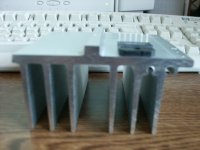
carlosfm said:Great, but those 'heatsinks' are too thin...
Depends on the voltage though.. If hes running it at 10-20V the thing wont even get warm.
Plus it kinda connects to the chassi.
thomas997 said:Depends on the voltage though.. If hes running it at 10-20V the thing wont even get warm.
Yes, at lower voltages it won't get hot.
thomas997 said:Plus it kinda connects to the chassi.
If the heatsink is thin there will be a "hot-spot" right on the back of the chip. The heat doesn't spread properly.
The heatsink will be almost cold at the extremes, and
 on the chip. Even if it's connected to the chassis.
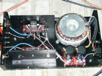
budwiser said:Opppps Tranny is 25-0-25. I have 37v coming out of the PS board.
budwiser said:Looks like I need to rethink my heat sinks real quick.
You do.
This is no Dynaco.

carlosfm said:If the heatsink is thin there will be a "hot-spot" right on the back of the chip. The heat doesn't spread properly.
The heatsink will be almost cold at the extremes, and
Would you mind providing a reference to support this statement?
I've noticed that gaincloner's have a penchant for thick heatsinks.
As far as my research shows, a heatsink's thermal transmission (degrees/watt) depends on it's surface area and finish, and has nothing to do with it's mass. In fact, mass will increase it's thermal inertia, making the heatsink heat up and cool down slower. Take a look at an air conditioner or car radiator: you won't find any massive conducting structures, just LOTS of surface area from LOTS of extremely thin fins.
- Eric
Eric Weitzman said:Would you mind providing a reference to support this statement?
Yes.
My post, your quote.
Eric Weitzman said:I've noticed that gaincloner's have a penchant for thick heatsinks.
I thought it was very obvious, but here it goes...
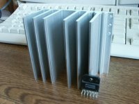
If you use transistors you can spread them through a heatsink.
One small chip concentrates the heat on a single point.
 This is also the reason for the sligh less power of the LM4780 against the LM3886, even if in practice it has two of them inside.
The 2-channel LM4780 concentrates the heat of two LM3886s on a single, small package.
A thin heatsink with no fins doesn't spread the heat away from the chip.
I've been there, done that, years ago.
You can burn your finger and leave a peace of your skin on the heatsink right on the back of the chip. Right next to it, it's just warm.
Eric:
".... car radiator: you won't find any massive conducting structures, just LOTS of surface area from LOTS of extremely thin fins."
I don't think this a very valid comment relating to the Dyna heat sinks.
The reason for the thin fins is to maximize the surface area to the air which is passing by at a high velocity. Inside the radiator ( if you like, on the other side of the fins) you have a moving liquid which has a very high specifiic heat. This combination allows very rapid heat transfer to the air, from the fluid either water or freon (in a liquid state). In other words the thermal resistance is low.
The thickness in a GC heatsink has to be thick enough to rapidly spread out the heat, from the CHIP which is a concentrated heat and rather tiny heat source Perhaps an analogy would be a thick enough conductor for high current in an electrical circuit.
If we had a very thin heat sink for GC with water passing by this would work as well.
carlosfm said:If you use transistors you can spread them through a heatsink.
One small chip concentrates the heat on a single point.
There are single transistors in TO-220 packages with comparable dissipation to the LM3886, such as the IRF9Z34N power mosfet, which can dissipate 68 watts. The spec sheet (just like the LM3886 spec sheet) is silent on the question of thickness.
I have never come across a spec sheet for a device that said how "thick" the heatsink had to be, only the thermal resistance (TR). It appears that if a heatsink's TR is 1 degree per watt, it's thickness is irrelevant.
carlosfm said:A thin heatsink with no fins doesn't spread the heat away from the chip.
I've been there, done that, years ago.
It was clearly your folly to not have fins on your thin heatsink. It's TR would have been extremely high, since TR is proportional to SURFACE AREA (not thickness AFAIK).
carlosfm said:You can burn your finger and leave a peace of your skin on the heatsink right on the back of the chip. Right next to it, it's just warm.
All that matters is the junction temperature of the transistors on the chip. This should be kept below 155 degrees on the LM3886. It doesn't matter if the heatsink burns your fingers at 150 degrees under the chip if it has the right TR. There's a chart on page 14 of the LM3886 spec sheet showing minimum TR for various ambient temperatures and power levels. You may want to extend the life of the component with lower TR, but lower TR has nothing to do with thickness.
Carlos, I was truly hoping for a reasonable answer from you that might have explained your assertion. This idea of "spreading heat" is naive. IIRC my high school physics, if the temperature gradient is high, the heat will be conducted away even faster.
Anyone interested in the subject of heatsinks may like to review http://sound.westhost.com/heatsinks.htm. The author, like all other sources I've read (except carlos) is mute about thickness.
Precisely. The thermal resistance is low. The way to accomplish this is with large surface area and fast moving air. I have never seen thickness or mass of the heatsink mentioned in any document I've read as a factor in increasing thermal resistance.SheldonD said:Eric:
".... car radiator: you won't find any massive conducting structures, just LOTS of surface area from LOTS of extremely thin fins."
I don't think this a very valid comment relating to the Dyna heat sinks.
The reason for the thin fins is to maximize the surface area to the air which is passing by at a high velocity. Inside the radiator ( if you like, on the other side of the fins) you have a moving liquid which has a very high specifiic heat. This combination allows very rapid heat transfer to the air, from the fluid either water or freon (in a liquid state). In other words the thermal resistance is low.
BTW, the fact that the coolant is a liquid or freon has little to do with the thermal resistance, and everything to do with transporting the heat from the source to the cooling device. The surface area of the contact between the piping and the fins determines the TR of that junction similar to the TRjc of a semiconductor device.
Assuming, for the sake of argument, that the thichness of a HS does matter, how much does the material the HS is made out of matter? For instance, could a copper sink be made of thinner material than something else, assuming that heat moves through copper more easily than other substances?
I ask this as I have a sheet of copper that is 4"x10"x0.25" that I was thinking of using. It has lots of surface area per volume, so it seemed ideal to me. But if this is inadequate, i'll find something else.
-d
I ask this as I have a sheet of copper that is 4"x10"x0.25" that I was thinking of using. It has lots of surface area per volume, so it seemed ideal to me. But if this is inadequate, i'll find something else.
-d
dsavitsk said:Assuming, for the sake of argument, that the thichness of a HS does matter, how much does the material the HS is made out of matter? For instance, could a copper sink be made of thinner material than something else, assuming that heat moves through copper more easily than other substances?
I ask this as I have a sheet of copper that is 4"x10"x0.25" that I was thinking of using. It has lots of surface area per volume, so it seemed ideal to me. But if this is inadequate, i'll find something else.
Here's a quick'n'dirty formula from Rob Elliott's web page I listed above to determine TR for a heatsink:
TR = 50 / squareroot(A), where A is area in square centimeters.
So your copper sheet, assuming both sides are exposed to outside air, would have TR=2.2^C/w.
Looking at the chart on page 14 of the LM3886 spec sheet, you could run the amp at about 38 watts total dissipation if the outside air temperture is 25^C. The case temperature of the chip would be about 105^C. If you were driving 8 ohm speakers, you could use a +/-38VDC supply and get about 28W audio power. You could get up to 60 watts dissipation at this voltage, but you'd need better heatsinking with lower TR.
There's also a link on that page to a site for building your own heatsinks from folded sheet metal.
I don't think the material's inherent TR is that big an issue as long as it is significantly smaller than than the TR between the heat sink and air. Unfortunately, Rod Elliott doesn't have any data on the metals per se.
"I ask this as I have a sheet of copper that is 4"x10"x0.25" that I was thinking of using. It has lots of surface area per volume, so it seemed ideal to me."
copper will move heat about 2x as fast as aluminum, there is anice article referencing CPU heatsinks at
http://www.overclockers.com/articles223/index.asp
http://www.overclockers.com/articles223/index02.asp
On page 2 :
"Aluminum will have a higher temperature difference between the point of contact and the heatsink extremities. This becomes and important factor because the heat must be removed from the heatsink along...."
This supports Carlos' contention that one could overheat the chip.
You have to consider that the heat flow at the contact between chip and heatsink is in three dimensions. It is quite possible that the heat flux density is too high at the chip and therefore the thermal resistance is too high, simply because the sink thickness is too small. Again similar to an undersized wire for electrical currents
I believe your 0.25 inch thickness is much more than required, as to the consideration brought up by Carlos. The total heat capacity will hav
e to be calculated.
- Status
- This old topic is closed. If you want to reopen this topic, contact a moderator using the "Report Post" button.
- Home
- Amplifiers
- Chip Amps
- Legacy GC with new snubber PS