A tiny voltage change on the cathode will affect the bias on the tube causing a bigger than normal change in current through the tube.
Let's throw some numbers at it. We can examine the input stage to a power amp using voltage amp -> split load inverter, since that's where you're likely to have the greatest swing. A 12AT7 is a common choice, so let's go with that. Put 120k on the plate. So to get 20V of swing, the current change is 0.16mA. The input voltage will be something like 0.4V.
Now, one can swamp any current changes in the LED by using my resistor-from-B+-to-cathode trick, but for the sake of discussion, let's not. The AC impedance of a red LED will be on the order of 7R at a "normal" plate current for 12AT7. So the voltage swing across it will be about 1.1mV, which is about 0.25% of the input voltage. If the LED nonlinearity at that tiny current swing were 10% (it's not), we're talking about 0.025% added distortion, which is considerably smaller than that contributed by the tube. The actual number will be even smaller.
If we do my resistor trick so that the LED current is 10mA, the impedance is now 4R. So we've dropped the added distortion by nearly half. And at smaller signal swings, the effect of the LED nonlinearity gets even smaller, as is true with higher plate loads. Thus the crazy-low distortion of my phono stage.
Lower distortion, higher gain, lower output impedance. Compared to bypassed resistor, faster recovery from overload, flat response to DC.
What can you say to that?
")
This has also confirmed my findings with the better drive.
Regards
M. Gregg
Now, one can swamp any current changes in the LED by using my resistor-from-B+-to-cathode trick, but for the sake of discussion, let's not.
Can you explain this trick please? Do you have a reference somewhere that I can look at?
Thanks
Charlie
I've posted it a few times before (and I notice that it has found a place in the latest edition of Valve Amplifiers); it's pretty self-explanatory, and I don't claim originality. Just run a resistor from B+ to the cathode to get a higher LED current. For example, let's say you have a red LED (1.7V) biasing a 12AX7 stage running 1mA, with a 200V supply. To get the LED to a flatter part of the Vf versus If curve, you might want the LED to have 10mA running through it. We supply the extra 9mA from a resistor, which can be calculated by Ohm's Law- R = V/I = (200-1.7)/0.010 ~ 200/0.01 = 20k.
As a practical matter, I haven't seen much difference when the plate loads are reasonably high (i.e., running close to constant current).
Just run a resistor from B+ to the cathode to get a higher LED current. For example, let's say you have a red LED (1.7V) biasing a 12AX7 stage running 1mA, with a 200V supply. To get the LED to a flatter part of the Vf versus If curve, you might want the LED to have 10mA running through it. We supply the extra 9mA from a resistor, which can be calculated by Ohm's Law- R = V/I = (200-1.7)/0.010 ~ 200/0.01 = 20k.As a practical matter, I haven't seen much difference when the plate loads are reasonably high (i.e., running close to constant current).
You need to bear in mind that the a resistor is not a direct replacement for the LED. A LED is functionally eqivalent to a resistor plus a bypass cap, typically an electrolytic.OK,
So how does that compare with a resistor in place of the LED?
Regards
M. Gregg
So - a resistor (unbypassed) in the cathode provides local feedback and reduces gain. Bypassing resistor with a cathode will retain same quiescent bias point, but will tend to reject signal voltage changes, hence providing a psuedo voltage source - so no local feedback, higher gain but also higher distortion, due to reduced feedback and capacitor non-linearities. A LED mimics the voltage source (assuming small dynamic impedance), retaining the gain of the bypassed resistor, but ditching the yucky electro. So for tubeheads who say that they don't want semi-conductors in their circuits, the options are a battery or an electro bypass cap. A simple unbypassed resistor is NOT equivalent.
Likewise, I've run 6N1P, 6N2P, 6N3P, and 6N23P with LED bias and current source as anode load and the distortion figures were consistently lower than the equivalent biased resistor load, resistor or resistor and cap in cathode circuit.
I used both HP spectrum analyzer and PC with sound-card for distortion measurements and to look at harmonic distribution.
I used both HP spectrum analyzer and PC with sound-card for distortion measurements and to look at harmonic distribution.
i blame it all on SY
Yeah, he twisted my arm and made me do this:
These camera phone flash SMD LED's have the lowest dynamic resistance of anything that I have tested, but I don't know what they are or where to get them. They came from a dumpster dive. They have more dynamics than the cap / resistor combo that it replaced.
Be aware that replacing the cap / resistor combo with LED's (or zeners, or other constant voltage circuits) essentially converts a cathode biased circuit to fixed bias. The grid resistors must be sized accordingly to avoid grid current induced runaway.
Attachments
Well,
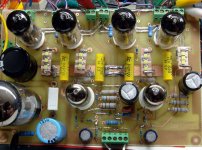
The first stage now has one yellow and one red LED in the cathode + MU stage..And it sounds very "Good" the Bass is more defined..I now have six LEDs and a diode under the board...
Worth the effort..Yes!
Would I take them out NO...you gotta be joking..LOL
Just got the do some more work on the Gyrator...
Regards
M. Gregg
M Greg: OT question.
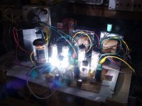
Are you sitting on a dinosaur and is Nibiru in the background ?
Don't you have your own Luck Dragon and wisdom pearl?
I thought we all had one..LOL
Its not so cold with valves...they can melt your heart...
Regards
M. Gregg
Interesting if not quizzical.
I can not get to the fourth page of this thread even though it shows as existing.
George deleted a post and added it back. Did something go wrong in the process?
Its probably because your already on it...LOL
Regards
M. Gregg
Just don't use them to bias up CCS.
Shoog
You have got to expand this...what have you found?
Regards
M. Gregg
M. Gregg, I could post to the thread, but not see it.
Problem was in my browser. I had to reboot and flush the history and cookies and log in again to clear it.
Thats strange.. to effect the browser..
Any Ideas what Shoog is refering to?
Regards
M. Gregg
- Status
- This old topic is closed. If you want to reopen this topic, contact a moderator using the "Report Post" button.
- Home
- Amplifiers
- Tubes / Valves
- LED's in the cathode..