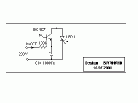
What abt having an blinking LED ? You don't need high voltage capacitor,bleeder resister and negligible power wastege..
See the circuit attached:
Brief discription:
When 230volt a/c is applied, it charges C1 (100Mfd/16Volts) until the transister breaksdown and charge stored in the capacitor is transferred to Led which lights,until the capacitor discharges and the transistor goes to off state and the LED is off,until the next cycle is started again.
For 110 volts reduce resistor to 47Kohms 1/4 watts.
for 230 volts use 1/2 watt resistor.
Any small signal transistor will work for T1 Eg:2N2222 etc
IT IS DANGEROUS TO TOUCH THE CIRCUIT WHEN POWERED.IT IS DANGEROUS TO TOUCH THE CIRCUIT WHEN POWERED.
THIS Led will blink only when the voltage is above 160volts AC.
Hi,
you have a problem.
1.) you need a >400V diode in series with the LED.
2.) the voltage drop across the LED+Diode ~4V.
3.) the voltage drop across the series resistor ~ 226Vac half wave rectified.
4.) the power to be dissipated ~ 226V * 50% * 0.35A ~40W
5.) the power resistor is at mains voltage.
you have a problem.
1.) you need a >400V diode in series with the LED.
2.) the voltage drop across the LED+Diode ~4V.
3.) the voltage drop across the series resistor ~ 226Vac half wave rectified.
4.) the power to be dissipated ~ 226V * 50% * 0.35A ~40W
5.) the power resistor is at mains voltage.
Fever - I would definitely use a transformer / wallwart, and turn that into a conventional low-voltage DC project.
One little mistake and you are dead, and then some.
NB. 350mA at 240VAC is over 80W ...even with current limiting, that's a significant amount of power, and therefore a fire risk too...
One little mistake and you are dead, and then some.
NB. 350mA at 240VAC is over 80W ...even with current limiting, that's a significant amount of power, and therefore a fire risk too...
Hi,
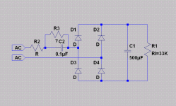
You could use a capacitive supply with a full wave rectifier: see picture.
For 350mA at 230V/50Hz, C2 would be 5.6µF, D1 to D4 a 1A rectifier bridge, R2 a 10ohm/3W WW resistor and R3 a 220K/0.5W.
5.6µF is a bit large for "electronic" 250Vac X capacitors, but can easily be found in electrotechnical applications for induction motors, fluorescent tubes ballasts, etc.
Rl would be your LED(s). The beauty of this circuit is that it is an almost perfect current source, and you can use any number of LEDs at the output.
Don't omit C1, it absorbs the current surge at the power-on.
Almost no power is wasted with this PSU.
Attachments
Hi,
I'm very new to the field of electronics and trying to learn from online resources so forgive me if the questions are stupid, but could someone please explain what is the purpose of R2 in the above diagram proposed by Elvee and why does it have to be WW?
Also, to my understanding using capacitor to drop voltage with such low resistance would result in rather poor power factor of the circuit. Am I right? Is it something to be concerned about, or it can be disregarded for such low currents?
If not, how can the power factor be corrected?
I want to monitor the presence of voltage on each of the three phases in my house (230/415Vac). We suffer very frequent power cuts.
I can put in a diode followed by a resistor then a LED.
The resistor dissipates quite a lot of power. or
I could use a constant current source but it would need to be Hi Voltage. or
I could wire in three transformers & then LED at low volts.
I don't like any of my solutions.
Can anyone suggest a cheap, safe & simple circuit?
regards Andrew T.
Depends on what you class as SAFE.
The simplest solution is an X rated cap with a diode, a resistor and an LED.
This is inherently DANGEROUS unless you take precautions about ensuring everything is insulated.
The safest solution is with a small transformer, a diode and a resistor,
This is inherently SAFE but is ungainly and inelegant.
Hi,
I'm very new to the field of electronics and trying to learn from online resources so forgive me if the questions are stupid, but could someone please explain what is the purpose of R2 in the above diagram proposed by Elvee and why does it have to be WW?
Also, to my understanding using capacitor to drop voltage with such low resistance would result in rather poor power factor of the circuit. Am I right? Is it something to be concerned about, or it can be disregarded for such low currents?
If not, how can the power factor be corrected?
The power factor is really a non issue with so small a cap (the 0.1uf).
R2 is often used on this type of circuit although here it is not really needed. Usually its a small carbon type...
If the 500uf cap were ommited and just an LED used then its possible at switch on that (depending on where in the cycle the mains was) that the peak current of the LED could be exceeded. The 500uf cap absolutely swamps that issue though.
R3 across the 0.1uf cap must be a high voltage resistor. Resistors do have max voltage ratings, even if the wattage is well withing spec. Sometimes good practice to use two series connected ones. Its purely to discharge the 0.1uf on switch off to prevent a small shock if you touched it later.
How safe is using a led at mains potential, as far as isolation is concerned?
I am talking about an application having the following:
(1) earthed metal box
(2) resistor-diode-led combination driven directly from mains for a specific purpose
I am considering the possibility of mounting the led onto the earthed enclosure, via plastic insulation (Bezel etc). How safe is it?
I am talking about an application having the following:
(1) earthed metal box
(2) resistor-diode-led combination driven directly from mains for a specific purpose
I am considering the possibility of mounting the led onto the earthed enclosure, via plastic insulation (Bezel etc). How safe is it?
If the LED will be at mains potential then it needs to be behind a lens, not exposed outside the box. Then someone has to break both the lens and the LED to expose themselves to danger.
My guess is that LEDs themselves, and the bezels intended for them, are not necessarily safe for continuous mains AC stress unless the datasheet says so. A small air gap will ensure safety.
My guess is that LEDs themselves, and the bezels intended for them, are not necessarily safe for continuous mains AC stress unless the datasheet says so. A small air gap will ensure safety.
just buy a safety rated pilot light folks 110 or 230 VAC
http://www.farnell.com/datasheets/1761263.pdf
http://www.farnell.com/datasheets/1761263.pdf
I can also house the led inside the box and just drill a hole, putting the led well away from it but ensuring that you are able to see whether it is on or not through that hole. I just need a rough indication, not super-high-tech indication. 
Infinia thanks for the link, I have considered this solution but maybe it takes too much space for my needs. I will consider it again anyway.
Infinia thanks for the link, I have considered this solution but maybe it takes too much space for my needs. I will consider it again anyway.
Holes in boxes containing mains voltage can be dangerous. Cover the hole with something transparent.
I plan to drill some holes on the top of my enclosure to ensure good cooling. Some sets of 3mm spaced adequately, bottom-top. I thought about using these holes as paths to see whether the LED is on.
I agree on your point, but how can then we provide cooling holes for an appliance, if it will be using mains? Most power amps have them. I will not expose mains inside the box (the led is planned to be the only "exposure") and I plan to house mains circuitry inside a plastic inflammable box. So exposed mains will not exist. But for some reason, I think that my practice does not satisfy your comment. Am I wrong?
That should be OK. Keep the holes a reasonable distance away from any exposed mains.
"Inflammable" is a strange English word: it looks like a negative (not flammable) but is actually a positive (very flammable). Safety people here are trying to get rid of the word and just use 'flammable' instead. I think you meant to say 'non-flammable'?
"Inflammable" is a strange English word: it looks like a negative (not flammable) but is actually a positive (very flammable). Safety people here are trying to get rid of the word and just use 'flammable' instead. I think you meant to say 'non-flammable'?
- Status
- This old topic is closed. If you want to reopen this topic, contact a moderator using the "Report Post" button.
- Home
- Design & Build
- Parts
- LED on mains voltage?


