It is indeed possible to use an LED in place of the cathode resistor and capacitor in the Simple SE and the Tubelab SE. As with any amp modification some experimenting is necessary. There is a fairly wide variation in the 12AT7's used in the Simple SE and a really big variation in the 5842 used in the Tubelab SE, which is the reason for the pot. LED's are usually consistent from device to device within the same batch, but exhibit some variation in voltage drop from batch to batch.
The easiest way to do this is to build the amp normally, and then measure the plate voltage on the driver tube. Remove the resistor and cap (or resistor cap and pot) and substitute in several different LED's until a similar plate voltage is reached. If you have several driver tubes, you could try rolling several of these through to find the best combination of tube and LED. I have done this on both amps. The Tubelab SE took a lot of tube and LED swapping to find a good combination.
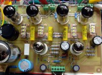
It is possible to use LED's in the output stage on some amps, but this is really only practical with tubes that work with a low bias voltage at relatively low current. The EL84 is one of those tubes, as evidinced by SY's RLD. Of course I had to try this too, so I made the WLD! It is a prototype Simple P-P board. In place of the cathode resistors I used a little ceramic substrate with 3 SMD white LED's in series.
The easiest way to do this is to build the amp normally, and then measure the plate voltage on the driver tube. Remove the resistor and cap (or resistor cap and pot) and substitute in several different LED's until a similar plate voltage is reached. If you have several driver tubes, you could try rolling several of these through to find the best combination of tube and LED. I have done this on both amps. The Tubelab SE took a lot of tube and LED swapping to find a good combination.
It is possible to use LED's in the output stage on some amps, but this is really only practical with tubes that work with a low bias voltage at relatively low current. The EL84 is one of those tubes, as evidinced by SY's RLD. Of course I had to try this too, so I made the WLD! It is a prototype Simple P-P board. In place of the cathode resistors I used a little ceramic substrate with 3 SMD white LED's in series.
Attachments
Last edited:
Did you measure the dynamic impedance of the white LEDs?
edit: from the I/V graph in the datasheet for a VAOS SP4W4, which looks a lot like yours, the dynamic impadance at 100mA looks like about 2-3 ohms at Vf of 3.2V. Pretty darn good!
Hmm, would you consider replacing the 2 red led's in the impasse with one white one?
I am also wondering whether it would be desirable to reconfigure the RLD display in the manner of "Ol' Betsy" with red, white and blue LED's. Think of the combinations
")
The thought has not escaped me. But the dynamic impedance looks much higher at those low currents.
Red bottom lighting of the tubes in the RLD is pretty attractive, but not having to solder 150 leads or so is pretty attractive as well. The SP4W4 are reasonably cheap, too, $2.50-$3.00. That's $8-9 per channel for an RLD.
Red bottom lighting of the tubes in the RLD is pretty attractive, but not having to solder 150 leads or so is pretty attractive as well. The SP4W4 are reasonably cheap, too, $2.50-$3.00. That's $8-9 per channel for an RLD.
How about a couple of the Cree LED's used in lightbulbs? http://www.cree.com/Products/pdf/XLampXP-E.pdf
Hey George, didn't you use something similar?
Hey George, didn't you use something similar?
Did you measure the dynamic impedance of the white LEDs?
I didn't until I saw this post right before I left work. I connected one (unmounted, no heat sink) across a fancy digital power supply and stepped the current in 10 mA steps and recorded the voltage. The data is below.
10 mA 3.00 V
20 mA 3.09 V
30 mA 3.14 V
40 mA 3.19 V
50 mA 3.22 V
60 mA 3.25 V
70 mA 3.27 V
80 mA 3.28 V
90 mA 3.29 V
100 mA 3.30 V
110 mA 3.31 V
120 mA 3.315 V
150 mA 3.32 V
200 mA 3.33 V
The dynamic resistance drops with increasing current (expected) and is 2 to 3 ohms over the range seen in an EL84. The ultra low resistance in the 120+ mA range isn't real. The LED is frying!
Hey George, didn't you use something similar?
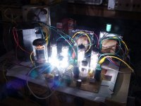
Unfortunately I have no idea what the specs or the vendor for this part is. A few years ago there was a massive layoff at work (350 engineers in one day). The clean up crews came through afterwords and threw most of the unmarked stuff in the trash. These looked like vendor samples since they were an unreeled strip. I am guessing that these were intended for the flash in a camera phone, so they were not made for continuous duty. The dynamic resistance looks very low above 80 mA but there was some serious chip heating going on which got worse as I turned up the juice. The white light turned bluish at 150 mA and the chip started smoking at 200 mA. The readings and the light returned to normal after several seconds at 70 mA so that is probably a safe current. I had the LED's in my Simple P-P for several weeks until I broke one of the ceramic substrates.
Last edited:
The white light turned bluish at 150 mA and the chip started smoking at 200 mA. The readings and the light returned to normal after several seconds at 70 mA so that is probably a safe current. I had the LED's in my Simple SE for several weeks until I broke one of the ceramic substrates.
LOL...yeah those are not intended for continuous duty at full intensity. They will self-destruct. The one's I have in my cube right now are driven with 180-200mA each (there are two) for a maximum of 200ms. In torch mode (continuous), they have to be current limited to 80mA. I'm one of the camera drivers guys, so I've blown up a few...only one by accident but that wasn't my fault...FL HW guys put an R0 where there should have not been one.
We have bigger ones too...this one dual module draws so much current at full intensity that we can't do GSM burst at the same time without tripping the current overload protection of the battery. The torch mode current is still in the <100mA category.
Last edited:
I don't know about yours but each one of these have two die inside each package.
That makes sense. They get pretty hot at 100 mA. I'm not so sure that the one I lit up today is still as bright as it was before I cranked it to 200 mA.
Back about 10 to 12 years ago I was working on a redesign of the first Nextel Pocket Phone. Blue LED's had been out for a relatively short time and they were still about $1 each. One of the ME's on the team successfully **'ed a vendor into giving him a hand full of samples. He proceeded to change out all of the keypad LED's in his phone for blue ones and then brought it to me because they weren't very bright. I explained to him that there were these things called resistors that slow down the electricity. Since blue LED's needed more electricity than green ones he needed some smaller resistors. He asked me what the smallest resistor was. I explained that there were zero ohm resistors, but that things would probably fry. He wanted some. The pocket phone used a 7.2 volt battery. Two LED's in series run off of raw battery supply. That phone (clear plastic housing) would light up a room. I got him to make me one. I still have it, and it still works!
I meant Simple P-P.
All Electronics has a surplus LED in their catalog (LED-912) for $.65 that can run at 70 mA continuous. It is red so it drops 2.5 volts. Google turns up the spec sheet which has the VI curve. The dynamic resistance is about 10 ohms. You need about 5 of these things for an EL84 which is 50 ohms. There has to be a reasonably priced LED that works as good as these camera phone chips, but I haven't found it yet.
They aren't specced at the typical current we use. They start at 100 mA and go to 700 mA. The dynamic resistance of the red and amber ones is straight and low. The resistance of the white and blue ones go up at low currents. They have one other serious drawback. They are about $10 each and you will need 12 or 16 of them for a Simple P-P. Cree has never been generous with samples even when a large cell phone manufacturer calls. Then in this economy nobody is right now.
In torch mode (continuous), they have to be current limited to 80mA
That makes sense. They get pretty hot at 100 mA. I'm not so sure that the one I lit up today is still as bright as it was before I cranked it to 200 mA.
I've blown up a few...FL HW guys put an R0 where there should have not been one.
Back about 10 to 12 years ago I was working on a redesign of the first Nextel Pocket Phone. Blue LED's had been out for a relatively short time and they were still about $1 each. One of the ME's on the team successfully **'ed a vendor into giving him a hand full of samples. He proceeded to change out all of the keypad LED's in his phone for blue ones and then brought it to me because they weren't very bright. I explained to him that there were these things called resistors that slow down the electricity. Since blue LED's needed more electricity than green ones he needed some smaller resistors. He asked me what the smallest resistor was. I explained that there were zero ohm resistors, but that things would probably fry. He wanted some. The pocket phone used a 7.2 volt battery. Two LED's in series run off of raw battery supply. That phone (clear plastic housing) would light up a room. I got him to make me one. I still have it, and it still works!
I had the LED's in my Simple SE for several weeks
I meant Simple P-P.
All Electronics has a surplus LED in their catalog (LED-912) for $.65 that can run at 70 mA continuous. It is red so it drops 2.5 volts. Google turns up the spec sheet which has the VI curve. The dynamic resistance is about 10 ohms. You need about 5 of these things for an EL84 which is 50 ohms. There has to be a reasonably priced LED that works as good as these camera phone chips, but I haven't found it yet.
How about a couple of the Cree LED's used in lightbulbs?
They aren't specced at the typical current we use. They start at 100 mA and go to 700 mA. The dynamic resistance of the red and amber ones is straight and low. The resistance of the white and blue ones go up at low currents. They have one other serious drawback. They are about $10 each and you will need 12 or 16 of them for a Simple P-P. Cree has never been generous with samples even when a large cell phone manufacturer calls. Then in this economy nobody is right now.
Last edited:
I don't know about yours but each one of these have two die inside each package.
Yeah, that sounds like the dual die ones I have. The back of the substrate often has a metalized finish to act as a reflector. Sometimes they are even bowl-shaped.
That makes sense. They get pretty hot at 100 mA. I'm not so sure that the one I lit up today is still as bright as it was before I cranked it to 200 mA.
Well, those specs include some sort of MTBF. I'm not sure how much peak current they can take assuming you stay within the thermal limits. Obviously for what we are talking about, you are going to want to stay well below that. Some substrates can be thermally bonded to a heat sink.
That phone (clear plastic housing) would light up a room. I got him to make me one. I still have it, and it still works!
I remember one brass board I had (FL HW again) had all the keypad LEDs clustered together near the display. It was so bright you could not look at the board while it was on. I think they were hooked to a GPIO instead of a PWM by accident. Had to put electrical tape over them.
When that camera flash LED went, it went with a bang and stank up the whole floor with a smell I hadn't experienced before. They are usually connected right to B+, but back in those days we needed a current limiting resistor because we didn't have these fancy driver chips that we have now.
There has to be a reasonably priced LED that works as good as these camera phone chips, but I haven't found it yet.
They are not cheap.
I have done a lot of reading about biasing the tubes using current sources and current sinks, but I think I still did not get it right.
What would be the problem in using the same circuit is used as a current source in the Simple SE also as a current sink at the cathode. You make two of them and put the tube in the middle.
Thanks,
Davide
What would be the problem in using the same circuit is used as a current source in the Simple SE also as a current sink at the cathode. You make two of them and put the tube in the middle.
Thanks,
Davide
- Status
- This old topic is closed. If you want to reopen this topic, contact a moderator using the "Report Post" button.
- Home
- More Vendors...
- Tubelab
- LED instead of Cathode resistors