If you are keeping the original circuit, then 5751 are a good idea - anything to cut down the gain.
I have a stereo 20 which has had about 15 different circuits in it during its life. I took the view that the original circuit is a total waste of time and almost anything will sound better. So the first thing to do is strip out all the insides and rewire all the essentials with new wire - proper twisted pairs for the heaters and kept away from the signal runs. It can be a good idea to replace the tube sockets, which can deteriorate. I then rewired the circuit board for a newer and simpler circuit, taking out most of the yellow wire underneath the board so I could wire directly between components on the top of the board.
I personally hate global feedback on amps, so getting rid of that was the first design consideration. I continued to run the outputs in UL at first, but then rewired them in triode. Without global feedback you need very little gain so you can use any of the really good sounding lower gain 9 pin tubes - ECC99, 6N30, 6N1P, E80CC... Just use any simple Mullard type circuit,
I like to keep the look of the amp original - no hacking away at the metalwork. But it's a simple matter to put in two small 10H 100mA chokes in parallel underneath the mains transformer - the ones I used fitted perfectly on the end of the 4 bolts attaching the mains transformer, which I lengthened.
All the revised versions of the Leak sounded a lot better than the original - as well they should!
If I had a really tatty amp that I would not mind changing the shape of I'd use 807 tubes in triode - perfect for the OPTs. Morgan Jones has a neat mod for re-wiring the OPTs which is a worthwhile mod. I'd also then use DHTs in the input, like 3a5 which can be used simply with filament bias and then only needs a small transformer to feed three of them with a LM1084 as voltage reg or CCS. Maybe the existing heater circuit could even be used to produce the DC if it didn't hum.
andy
If you are keeping the original circuit, then 5751 are a good idea - anything to cut down the gain.
I have a stereo 20 which has had about 15 different circuits in it during its life. I took the view that the original circuit is a total waste of time and almost anything will sound better. So the first thing to do is strip out all the insides and rewire all the essentials with new wire - proper twisted pairs for the heaters and kept away from the signal runs. It can be a good idea to replace the tube sockets, which can deteriorate. I then rewired the circuit board for a newer and simpler circuit, taking out most of the yellow wire underneath the board so I could wire directly between components on the top of the board.
I personally hate global feedback on amps, so getting rid of that was the first design consideration. I continued to run the outputs in UL at first, but then rewired them in triode. Without global feedback you need very little gain so you can use any of the really good sounding lower gain 9 pin tubes - ECC99, 6N30, 6N1P, E80CC... Just use any simple Mullard type circuit,
I like to keep the look of the amp original - no hacking away at the metalwork. But it's a simple matter to put in two small 10H 100mA chokes in parallel underneath the mains transformer - the ones I used fitted perfectly on the end of the 4 bolts attaching the mains transformer, which I lengthened.
All the revised versions of the Leak sounded a lot better than the original - as well they should!
If I had a really tatty amp that I would not mind changing the shape of I'd use 807 tubes in triode - perfect for the OPTs. Morgan Jones has a neat mod for re-wiring the OPTs which is a worthwhile mod. I'd also then use DHTs in the input, like 3a5 which can be used simply with filament bias and then only needs a small transformer to feed three of them with a LM1084 as voltage reg or CCS. Maybe the existing heater circuit could even be used to produce the DC if it didn't hum.
andy
Andy.
You are way beyond me as for as the circuit is concerned. Don't know that much.
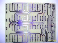
Tried to make a new precise PCB copy of the original without all the bottom wiring. The idea was: outer holes for wires - inner holes for silverpins.
What is best - hardwiring or PCB with cobberlines? Would like to refresh one of two amps - one original - one with new brown paint and Leak "marks" like "L" and "R" , "Input", ECC83 a.s.o.. Do you know the brown paint code? How do we make the "silkprint" on the paint?
Want to use EL84 - the type I can afford with best sonic sound! Is it possible for you to show the circuit you prefer for the Stereo 20?
Which Morgan Jones edition talks about Stereo 20 mod. ?
Many questions.
Gudmund
Attachments
If you are keeping the original circuit, then 5751 are a good idea - anything to cut down the gain.
You can cut gain more by using the 12AY7, while retaining the high RP and low gm.
If you want to restore Leak equipment, best to join the Leak users group - hjleak at Yahoo Groups.
I don't think I have any record of all the circuits I dreamed up. They were pretty simple - some kind of voltage amp first stage direct coupled to a differential pair with the second grid grounded. I then used russian teflon caps to couple to the outputs.
The Morgan Jones OPT mod came from some thread or other - can't remember as it's long ago. I have a pdf of it somewhere. Maybe it's possible to do a search here or it may have been the Audio Asylum. May have been the Leak users group. It direct wired the transformer for 4 ohms so you no longer had the switchable impedences on the output.
Andy
Here's a well thought out circuit to use with a proven track record. Would go nicely in a stereo 20. Should also be plenty of posts here on it if you search under Poinz, Eric Kingsbury and Musical Machine. Plus Eric is an absolutely lovely guy and it's a pleasure corresponding with him.
http://www.audiotropic.net/Products/machine.html
andy
http://www.audiotropic.net/Products/machine.html
andy
Hi is this the opt mod you refer too?
 One of the best things you can do with a Leak is to improve the output transformer. Most loudspeakers these days are nearer to 4 Ohm than 8 - especially those using a pair of bass drivers. But if you set a Leak to match to a 4 Ohm load, you only use half of the secondary.
If you have the courage to take the shells off the output transformer, you will find that the individual windings are terminated on cardboard strips glued to the coil. You can then reconnect them as shown in the right hand diagram so that you use both windings - which makes for a transformer with reduced leakage inductance - a better transformer, and it cost only a little time. You will probably go one step further and connect new wires directly to the transformer and throw away the phenolic tagboard at the base of the transformer and its associated old wires.
Having tweaked the secondary, you'll probably look at the primary and see that it's possible to replace the wires there too. The PVC-covered wires solder to little solder tags inside the paper windings, and it's perfectly possible to desolder them and replace them with longer wires that go directly to the valve sockets
here are three output windings. Two are already in parallel. For the third, EC8010 is right. The third winding - looking at EC8010's useful diagram - starts at the 4 ohm tap and goes up to the 15 ohm tap. this winding should be re-connected, the 4 ohm side to negative and the 15 ohm to positive. I hope this is clear
If you have the courage to take the shells off the output transformer, you will find that the individual windings are terminated on cardboard strips glued to the coil. You can then reconnect them as shown in the right hand diagram so that you use both windings - which makes for a transformer with reduced leakage inductance - a better transformer, and it cost only a little time. You will probably go one step further and connect new wires directly to the transformer and throw away the phenolic tagboard at the base of the transformer and its associated old wires.
Having tweaked the secondary, you'll probably look at the primary and see that it's possible to replace the wires there too. The PVC-covered wires solder to little solder tags inside the paper windings, and it's perfectly possible to desolder them and replace them with longer wires that go directly to the valve sockets
An externally hosted image should be here but it was not working when we last tested it.
here are three output windings. Two are already in parallel. For the third, EC8010 is right. The third winding - looking at EC8010's useful diagram - starts at the 4 ohm tap and goes up to the 15 ohm tap. this winding should be re-connected, the 4 ohm side to negative and the 15 ohm to positive. I hope this is clear
I run a cd player direct into my amp (no pre amp) player has a vol control. To bring the players output down i just use a simple voltage divider built into the interconnects rca jacks at the amp end -20db. it has allowed me to use the it without having to set about the amp with a soldering iron and keeping it totally original
You can cut gain more by using the 12AY7, while retaining the high RP and low gm.
Eli
Looked at a datasheet for the 12AY7 before answering you. Found Mu=44 at Duncan's page. Could this type be used in the original circuit without changes? - a short explanation of Rp and low GM ? Rp = Plate resistance? - GM = Gain?
Sy
Well - this is a hobby - need to buy the 3. edition.
Andy
Untill the experience with the Stereo 20 comes up, I have to work with a circuit close to the original. - saw the note about teflon capasitors.
The AudioTopic amp has high built quality - could not find the circuit - Shall remember Poinz and Eric. Have checked the Leak user group.
Stereo 20 may have insufficient circuits compared to newer designs - have though heard a standard Stereo 20 which played well at my friends setup.
Gudmund
RP is plate resistance and gm is mutual transconductance. The amplification factor (μ) can't be realized, as an infinite load is necessary. You can come quite close by using constant current source (CCS) loading.
Installing a 12AY7 instead of a 12AX7 as the I/P tube reduces open loop gain. However, in a circuit with sufficient open loop gain, loop NFB circuitry determines net gain. Look at the Stereo 20 schematic. A global negative feedback (GNFB) loop is present. R18 and R4 form the gain set pair. Reducing R18's value increases the % of the O/P voltage fed back and decreases the net gain.
Now comes the tricky part. C9 is present for phase compensation reasons. It shorts R18 out at high frequencies. The 1/2 power freq. (F3) Leak chose is approx. 66.3 KHz. As R18 goes down in value, C9's value must increase to keep F3 "unchanged".
RP is plate resistance and gm is mutual transconductance. The amplification factor (μ) can't be realized, as an infinite load is necessary. You can come quite close by using constant current source (CCS) loading.
Installing a 12AY7 instead of a 12AX7 as the I/P tube reduces open loop gain. However, in a circuit with sufficient open loop gain, loop NFB circuitry determines net gain. Look at the Stereo 20 schematic. A global negative feedback (GNFB) loop is present. R18 and R4 form the gain set pair. Reducing R18's value increases the % of the O/P voltage fed back and decreases the net gain.
Now comes the tricky part. C9 is present for phase compensation reasons. It shorts R18 out at high frequencies. The 1/2 power freq. (F3) Leak chose is approx. 66.3 KHz. As R18 goes down in value, C9's value must increase to keep F3 "unchanged".
The tricky part, if understanding you right, is that c9 and r18 works like a filter that turns the phase at higher frequences? If one want to determine the "net" gain we have to reduce R18! - Increase C9.
What about R4 - do we keep same value? C9 have to be increased - how much?
Is it difficult to calculate?
The 1/2 power freq. F3 Leak chose 66,3kHz - did not understand? Is it 66,3kHz -3dB point at approx 6watt??
Gudmund
Will changing out the 12AX7 actually change the gain significantly? Strikes me as "no." It will reduce the feedback and increase distortion, but the gain is set by the feedback resistors.
I'd either gut and rebuild, or keep the original and restore.
Agreed - on this level of valve knowledge. - Have to stay close to the std. circuit.
The tricky part, if understanding you right, is that c9 and r18 works like a filter that turns the phase at higher frequences? If one want to determine the "net" gain we have to reduce R18! - Increase C9.
What about R4 - do we keep same value? C9 have to be increased - how much?
Is it difficult to calculate?
The 1/2 power freq. F3 Leak chose 66,3kHz - did not understand? Is it 66,3kHz -3dB point at approx 6watt??
Gudmund
Sorry about creating confusion by using the term 1/2 power. R18 and C9 form a high pass filter. The frequency at which reactance and resistance are = goes by several names, including F3, "corner", and 1/2 power. This has nothing to do with the power O/P of the circuitry.
The law (formula) for RC filters follows immediately.
(2Π) (Fin Hz.) (C in Farads) (Rin Ω) = 1
Knowing any 2 of the 3 variables allows you to quickly compute the 3rd.
IMO, changing the value of R4 is not a good idea, as the bias conditions for the I/P triode will be altered.
Respectively, the OEM values for R18 and R4 are 12 KOhms and 100 Ω. Therefore, the fraction of the O/P voltage being fed back is approx. 0.008, which (IMO) is quite small. A seat of the pants guess for R18 and C9 is 4.7 KOhms and 470 pF. Use either NPO ceramic or NOS mica for C9. Unfortunately, there have been quality problems in current production silvered mica parts.
The OEM 1 MOhm value for R1 is not good. A low pass pole is formed by that resistance and the I/P triode's CMiller. As a consequence, HF info. loss occurs. Reduce R1 to 100 KOhms. Modern signal sources will have no difficulty in driving that value.
Well - as new here some terms are unknown. The formular is good to know.
Ok - I stay away from R4.
When you say NPO ceramic or NOS silvermica for C9 - does it mean that it is essential to be very precise at this point/component?
The info about R1 is good to have in mind - 100K it will have to be.
Thanks
Gudmund
When you say NPO ceramic or NOS silvermica for C9 - does it mean that it is essential to be very precise at this point/component?
The problem with current production silvered mica caps. is the delivery of parts well outside the 20% tolerance claimed. NOS "domino" style mica parts are true, within tolerance, to the claimed value. Many NOS mica caps. are not silvered, as silvering cost more in manufacturing. What is important is that the claimed value be correct, within tolerance.
The specific tolerance of the phase compensation cap. is not particularly important. Each amp section, due to difference in stray capacitances and parts (particularly the individual O/P trafo) really requires empirical optimization at the bench. The value of the phase compensation cap. is tweaked to get the best looking (tilt, ringing, overshoot, ...) 2 KHz. square wave on an o'scope.
BTW, if you are going to try 4.7 Kohms for R18, make C9 510 pF.
After rebuilt the Stereo 20 have to be tested on a scope - by a friend - Will try to get NOS silvermica.
Yes - would like to try the suggested values - Thanks for the calculation.
Gudmund
If I may intrude, what is C1 (0.001uF) for?
It has to be phase compensation of some kind. C1 combines with R4 to form a high pass pole. F3 for that pole is (sic) 1.6 MHz. That strikes me as being of little or no consequence at the frequencies of interest. Maybe it helps with ringing.

- Status
- This old topic is closed. If you want to reopen this topic, contact a moderator using the "Report Post" button.
- Home
- Amplifiers
- Tubes / Valves
- Leak stereo 20 modification