Triode_al,
my subjective experience with increasing feedback is similar to yours. Increasing fb makes sound more like "average" amp.
cleaner but lifeless.
From what i understand of hiraga's research into distortion he aimed for an "even spread" of harmonics.
From experience with my previous monstre i also found out that beefing up ps-lines on pcb and also pcb-connection between output-transistors(speaker-output) makes amp sound a lot better.
Groeten,
Klaas
Another thing is original parts...
I remember having had contact with someone who used BC560's in the schema etc, but the DC points didn't work out.
Anyway, if you would design a PCB, could you take into consideration the original parts/legs? Probably means adding some extra layout.
And if you could organise a group-buy, I suggest ordering fully through-metalised holes, military grade, so it is easier to replace components and soldering stays on better.
albert
Attachments
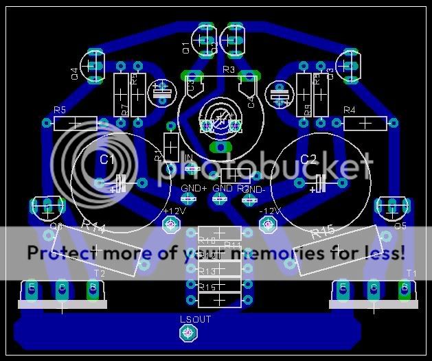
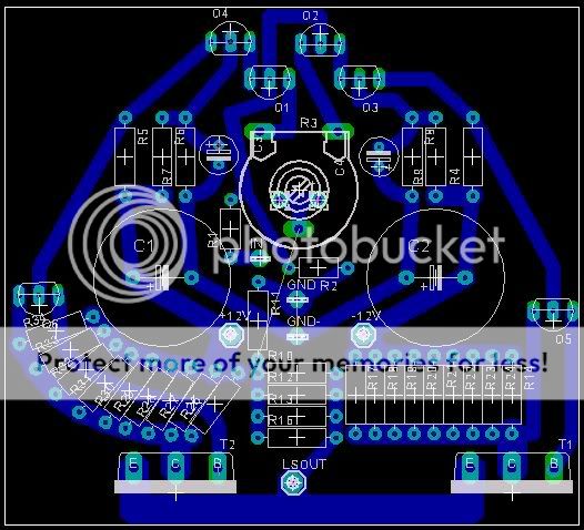
screenshot of "work in progress" (still didn't implement Upupa's proposed filtering of ps for input-stage, due to lack of time):
Any comments will be gladly appreciated

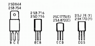
my monstre is using 2sj103-2sk246-bc560-bc660 and is working fine.
I will definately consider making pcb for original parts, right now i'm not even considering groupbuy - to me this is mainly learning experience- anyone who wishes to use my pcb-design , go ahead.
With kind regards,
Klaas
Any comments will be gladly appreciated
can you clarify on that Albert ? don't understand what you meanbut the DC points didn't work out.
my monstre is using 2sj103-2sk246-bc560-bc660 and is working fine.
I will definately consider making pcb for original parts, right now i'm not even considering groupbuy - to me this is mainly learning experience- anyone who wishes to use my pcb-design , go ahead.
With kind regards,
Klaas
Hallo Klass,
you are very busy on Easter sunday!
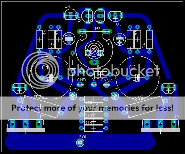
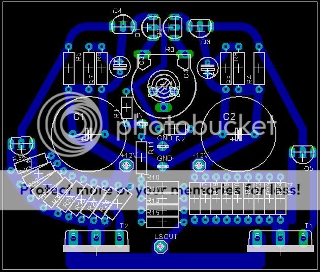
Turn Q1 +Q2 to the left for 90° and set the front of the trans`s to one common line (this had done a friend of mine). Thenit is easy to clip them on a cooper blade.
What is the benefit of splitting the emitter resistors and mount them this style?
Regards
Sam
you are very busy on Easter sunday!
Turn Q1 +Q2 to the left for 90° and set the front of the trans`s to one common line (this had done a friend of mine). Thenit is easy to clip them on a cooper blade.
What is the benefit of splitting the emitter resistors and mount them this style?
Regards
Sam
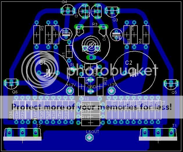
Sam, as i see it i could turn q1 and q2, but q3 is not possible.Also will destroy symetry on pcb (which i kinda like). I never had problems with dc-drift fyi. splitting emitter-resistors will mean very small inductance and increased reliability.only reason left-side is curved is keeping connection between q6 and t2 short.
placing r's on leftside almost gave me headache
With kind regards,
Klaas
placing r's on leftside almost gave me headache
With kind regards,
Klaas
masag said:Hallo Klass, ---
What is the benefit of splitting the emitter resistors and mount them this style?
Sam
Good to split the Emitor res's - they will get less inductance and even at 1 ohm and 0,7-1 amp they do get hot. Low heat is better, otherwise there will be temperature coefficients that will evidently temperature-modulation...
albert
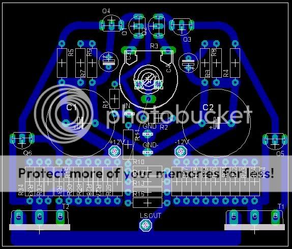
Thanks all again.This is what i came up with before i read your replies:
You see Upupas, jumper for feedback is there , nice and symmetrical.
I widened tracks in power-section because in my experience sound benefits a lot from wire on pcb.My guess is the widened tracks in combination with soldering all those enitter-resistors works as 'wire'.
Glad somebody noticed Piher pot,which is dreadfull to adjust.
On my very first pcb i posted here i already provided for soldering discrete r's instead of pot, but i will look into this.
Pls let me know what you guys think.
Sam, i'm using Eagle (unlimited version )
With kind regards,
Klaas
You see Upupas, jumper for feedback is there
, nice and symmetrical.I widened tracks in power-section because in my experience sound benefits a lot from wire on pcb.My guess is the widened tracks in combination with soldering all those enitter-resistors works as 'wire'.
Glad somebody noticed Piher pot,which is dreadfull to adjust.
On my very first pcb i posted here i already provided for soldering discrete r's instead of pot, but i will look into this.
Pls let me know what you guys think.
Sam, i'm using Eagle (unlimited version
)With kind regards,
Klaas
- Status
- This old topic is closed. If you want to reopen this topic, contact a moderator using the "Report Post" button.
- Home
- Amplifiers
- Solid State
- le monstre questions