I again violated one of the most important rules in DIY - Never Solder while tired...
I had been happily using a pair of Zappulse 2.1 modules and got a a bug in my butt to upgrade the power supply from single supply to dual mono...somehow I tripped up the rail wiring and saw a nice puff of smoke...took out my tweeters of my KEFs too.
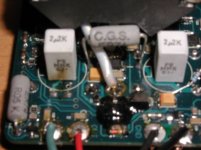
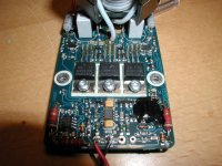
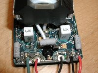
Anyway, I unhooked everything and went to sleep...next day I checked out the modules and saw the two resistors in front of the 2.2uf caps by the wiring inputs that looked charred...but all else from first glance looked OK...I reconnected everything (correctly) and got full rail voltage on the outputs.
After emailing LC Audio about some info and the resistor values (they were very protective of telling me anything value-wise) I replaced the two 20k resistors that I saw looked charred...LCAudio tech said he thinks its 20k, but not sure.
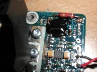
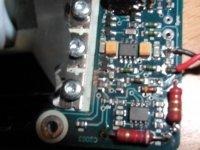
Anyway, it did not make a difference since I continue to get full rail voltage on the outputs...All the beefy resistors on the edges of the board look OK and seem to be fine, but wonder what else I could check/replace to get these two modules working again??
I gave up on the LC Audio tech, as all they could do is credit me $30 each module on a trade in for the newer modules...I didn't really like that option, and I have since built a UCD400AD that I am very happy with, but would still like to get these Zappulses working again...
Any help?
I had been happily using a pair of Zappulse 2.1 modules and got a a bug in my butt to upgrade the power supply from single supply to dual mono...somehow I tripped up the rail wiring and saw a nice puff of smoke...took out my tweeters of my KEFs too.
Anyway, I unhooked everything and went to sleep...next day I checked out the modules and saw the two resistors in front of the 2.2uf caps by the wiring inputs that looked charred...but all else from first glance looked OK...I reconnected everything (correctly) and got full rail voltage on the outputs.
After emailing LC Audio about some info and the resistor values (they were very protective of telling me anything value-wise) I replaced the two 20k resistors that I saw looked charred...LCAudio tech said he thinks its 20k, but not sure.
Anyway, it did not make a difference since I continue to get full rail voltage on the outputs...All the beefy resistors on the edges of the board look OK and seem to be fine, but wonder what else I could check/replace to get these two modules working again??
I gave up on the LC Audio tech, as all they could do is credit me $30 each module on a trade in for the newer modules...I didn't really like that option, and I have since built a UCD400AD that I am very happy with, but would still like to get these Zappulses working again...
Any help?
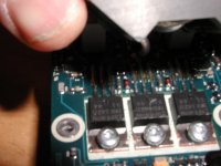
Well, you're lucky the FETs aren't damaged since the output is at the rail voltage. Resistors only fry when they can't dissipate the heat caused by the current flowing through them, so it would be wise to check any/all of the components in the circuitry associated with those resistors. If they were part of the input circuitry and there is an op amp in there you may want to check the op amp and any power supply circuitry for the op amp.
Clock Generator stopped?
I'm not very competent in electronics, but having just assembled my first ZAP 2.3SE amp, I have wondered about a question that is related to your problem.
The ZAP works by switching +/- voltage 400.000 times or so every second; the input signal controls the length of the +/- timeslices. When there is no input signal, and the output therefore should be 0, it is actually switching between + and - anyway, with equal timeslices.
What if the clock should stop? Hang up? Or, maybe be burned out? Would that draw a permanent voltage through one of the FET's?
Haakon.
Hmm,
Or if only the +rail is active, - rail dead, and no input, would you see +rail voltage on the output? And vice versa?
I will check (hopefully sometime tonight if possible) what the exact voltage is at outputs are when +/- rail and input are connected.
It's been a good 6 - 8 months since I had my little accident.
- Status
- This old topic is closed. If you want to reopen this topic, contact a moderator using the "Report Post" button.
- Home
- Amplifiers
- Class D
- LC Audio Zappulse 2.1 Issue