You save money on the wrong place! But this is my opinion!
You are doing a great service here. Two sided boards are essential. Those who don't like that can go elsewhere.
... here are the binaries...
For my part, finished, but up to you...
Am i the only one having problems with this zip folder?
It gives me an error everytime i try to unzip it.

But more importantly, thank you JSP for the work!
Hi JPS,
very nice offer, thank you!
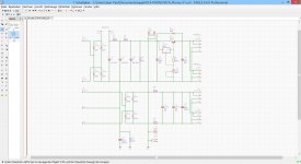
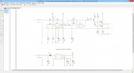
What I would like is a PCB for this bias servo circuit (I think the drawing is by Gingertube).
http://www.diyaudio.com/forums/tube...garter-push-pull-amplifier-2.html#post4460486
Each tube needs one of these servos; for stereo push pull one will therefore needs 4 of these circuits, and I think that putting everything on the same board would be good.
Maybe add a simple regulated (LM317 / LM337) power supply for the Opamps?
Cheers, Erik
very nice offer, thank you!
What I would like is a PCB for this bias servo circuit (I think the drawing is by Gingertube).
http://www.diyaudio.com/forums/tube...garter-push-pull-amplifier-2.html#post4460486
Each tube needs one of these servos; for stereo push pull one will therefore needs 4 of these circuits, and I think that putting everything on the same board would be good.
Maybe add a simple regulated (LM317 / LM337) power supply for the Opamps?
Cheers, Erik
Open with Winrar?!
Indeed, winrar worked like a charm.
Btw, what software did you use to create these?
I can't seem to open them with my Eagle 5.10 version
I can't seem to open them with my Eagle 5.10 version
The current freeware Eagle will let you view the files.
Hi Jean Paul,
I finished the schematics, all hand drawn. I hope that besides your generous offer of layouting, you are also willing to be a bit creative? I saw your work on the 4P1L amplifier, so I reckon you have experience and interest in tube circuits as well.
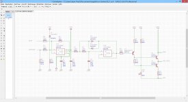
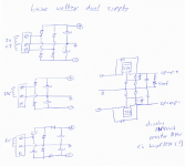
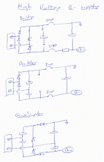
For both the low voltage dual supply and the B- supply I think it would be nice to be as flexible as possible, so I draw schematics for supplies based on diode bridge, doubler and quadrupler circuit. With the quadrupler circuit one can power the opamps with +/-12V DC using a (spare) 6,3V winding.
Optional: Sometimes it is good to use DC on the input tubes of an amp, and by using a more powerful PS and by putting the LM317 / LM337 on some heatsinks one can use the Opamp supply to feed the filaments.
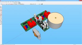
In the bridge, doubler or quadrupler circuit one will have to use either electrolytics or diodes, and probably some jumpers depending on which circuit one wants to use. I do think that leaving a 15mm diameter circle for every component will be enough to accomodate either the electrolytic cap or the diode?
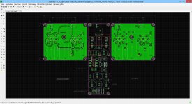
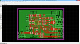
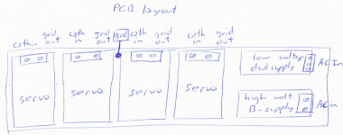
Finally, the layout for the PCB. I do think that a long and narrow board is easiest to place in a traditional tube amplifier, as the 4 output tubes (stereo push pull) are generally in one row.
For connectors I am a big fan of the 5.08mm MKDS series by Phoenix
https://www.phoenixcontact.com/onli...21&library=usen&pdfmode=direct&pdflanguage=en
and, as you see, I am quite oldfashioned: tubes, handdrawn schematics - so a throughhole board would be great!
Many thanks und freundliche Grüsse!
Erik
I finished the schematics, all hand drawn. I hope that besides your generous offer of layouting, you are also willing to be a bit creative?
I saw your work on the 4P1L amplifier, so I reckon you have experience and interest in tube circuits as well. For both the low voltage dual supply and the B- supply I think it would be nice to be as flexible as possible, so I draw schematics for supplies based on diode bridge, doubler and quadrupler circuit. With the quadrupler circuit one can power the opamps with +/-12V DC using a (spare) 6,3V winding.
Optional: Sometimes it is good to use DC on the input tubes of an amp, and by using a more powerful PS and by putting the LM317 / LM337 on some heatsinks one can use the Opamp supply to feed the filaments.
In the bridge, doubler or quadrupler circuit one will have to use either electrolytics or diodes, and probably some jumpers depending on which circuit one wants to use. I do think that leaving a 15mm diameter circle for every component will be enough to accomodate either the electrolytic cap or the diode?
Finally, the layout for the PCB. I do think that a long and narrow board is easiest to place in a traditional tube amplifier, as the 4 output tubes (stereo push pull) are generally in one row.
For connectors I am a big fan of the 5.08mm MKDS series by Phoenix
https://www.phoenixcontact.com/onli...21&library=usen&pdfmode=direct&pdflanguage=en
and, as you see, I am quite oldfashioned: tubes, handdrawn schematics - so a throughhole board would be great!
Many thanks und freundliche Grüsse!
Erik
Attachments
- Status
- This old topic is closed. If you want to reopen this topic, contact a moderator using the "Report Post" button.
- Home
- Design & Build
- Software Tools
- Layouting for free