Is it technically possible to develop a servo subwoofer using a laser system such as http://www.opti-cal.com/heads.html rather than a conventional accelerometer ?
If so what would the principle be like ?
All advise would be greatly appreciated !
Thanks !
Junia.
If so what would the principle be like ?
All advise would be greatly appreciated !
Thanks !
Junia.
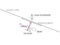
I have thought of such a system. It would use an infrared laser pointed at a 50% reflective mirror pointed at a 45 degree angle. The beam would bounce off of the woofer cone, and back through the the mirror into the reciever under the mirror. The beam would aim perpendicular to the woofer, and the woofer would have a white->black gradient printed on it. Parts would cost about 100 dollars for everything.
mazurek said:I have thought of such a system. It would use an infrared laser pointed at a 50% reflective mirror pointed at a 45 degree angle. The beam would bounce off of the woofer cone, and back through the the mirror into the reciever under the mirror. The beam would aim perpendicular to the woofer, and the woofer would have a white->black gradient printed on it. Parts would cost about 100 dollars for everything.
Hi
You've got my interest.
Care to share?
I think it is a bad idea. The sound output of the speaker is not proportional to the position of the cone, but rather its acceleration. So, if the position of the cone is detected, a double differentiation would be required in the feedback loop.
It appears much smarter to me to detect the acceleration of the cone in the first place.
(Nevertheless there was an article in JASA recently where someone had made something similar, detecting cone position)
It appears much smarter to me to detect the acceleration of the cone in the first place.
(Nevertheless there was an article in JASA recently where someone had made something similar, detecting cone position)
I cannot find a stable transfer function using acceleration as feedback, with a desired target function. The only unconditionally stable transfer function I get is when the feedback is position, if I were to use an accelerometer I would double integrate it.
If I were using an accelerometer, I would use this:
Digikey part number: MSP1001-ND
From the specs sheets of the analog devices imems devices some recommend, I believe that they have just barely enough measurement range, and the bandwidth is a little disappointing (i.e. only appropriate for subwoofer correction and equalization below one-two hundred hertz IMO). I believe that they could be used though.
If you have matlab, please look over the scripts I built to test variations of the feedback system. It takes a given target transfer function, and finds the resultant controller, taking into account the feedback transfer function and the speaker transfer function. I then use the matlab 'sisotool' which is a feedback system design tool, it reports on the stability of the resulting system, and can be used to experimentally move poles and zeros and explore the response.
I am somewhat concerned about the results some people post on feedback systems. To me, it appears on this forum that most do not take into account that the closed loop transfer function
with controller in forward path
= (speaker*controller) / (1 + speaker*controller*feedback)
with controller in feedback path
= (speaker) / (1+ speaker*controller*feedback)
So for those that just tack on feedback into their system, and just adjust the gain until its stable, they are completely changing the system transfer function.
Attachments
Svante said:I think it is a bad idea. The sound output of the speaker is not proportional to the position of the cone, but rather its acceleration. So, if the position of the cone is detected, a double differentiation would be required in the feedback loop.
It appears much smarter to me to detect the acceleration of the cone in the first place.
(Nevertheless there was an article in JASA recently where someone had made something similar, detecting cone position)
A laser has no "inertia" to speak of, at least as contrast with an accelerometer.
These are the parts I would use to build a laser system:
Half reflective mirror:
http://www.edmundoptics.com/onlinecatalog/displayproduct.cfm?productID=2035&search=1
Reciever:
Digikey search: OPT101
I haven't picked a laser yet, there are some good options in the range from 10-30 dollars
Search at digikey under "laser diode" or "infrared laser diode".
The color of the laser probably doesn't matter.
Edmun optics also sells mounting brackets for their mirrors if something could not be fabricated adequately.
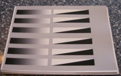
Here is a picture of the test patterns I had printed on matte paper.
I do not believe printer resolution is an issue due to bleeding which averages the value, and the beam size and pickup area which also averages the value. There are two styles depending on the ultimate setup I choose to use.
One advantage of this optical system is that the picture gradient can be modified to account for linear errors in the transducer system, and the gradient can also be modified to avoid subwoofer destruction. For example, different shades can be printed near xmax to eliminate destructive feedback, or to apply feedback to keep excursion under control.
Attachments
Here is a picture of my original concept. Not sure if this would fit in the motor to measure the dustcap. I had envisioned just using the cone as feedback. I feel this would work under the cone breakup mode, and possibly over the breakup if mounted in the correct place. As drawn, it depends on having a linear cone cross-section, however the gradient could be printed with a compensation function for a curved cone.
One advantage of this system over others is that there are no cords whatsoever hanging from the cone, and quite insignificant weight. Additionally, it can be done fairly cleanly with only analog processing (not necessarily a sound advantage, but developing a digital platform takes even more work).
The reason I have not yet gone further with this is that I am redeveloping my amplifiers/crossover to package them together in a more conveniant testing platform. Also, my subwoofers do not have a removeable baffle, therefore it is quite a pain to try this out. I was thinking about getting an IR beam and filter to maybe mount this on the front of the woofer to test. This project was on the back burner until I get my amplifiers changed. If someone wants to co-develop this stuff, it could be expedited.
I forgot to say, the feedback controller function ends up being in the form of two lead lag controller and a linkwitz transform, not to say that it is an actual linkwitz transform, just that is what the transfer function looks like.
Attachments
SVANTE
---So, if the position of the cone is detected, a double differentiation would be required in the feedback loop.---
Breden's sub (Electronics World ) draws me to suggest the possibility of a double integration at the input or a simgle integration at the input and a single differentiation in the feedback loop.
mazurek said:I cannot find a stable transfer function using acceleration as feedback, with a desired target function. The only unconditionally stable transfer function I get is when the feedback is position, if I were to use an accelerometer I would double integrate it.
???
Target function for what? The position of the cone? That is not interesting, the only thing that matters for the sound is the acceleration of it. If you design for a flat acceleration response, the sound frequency response will also become flat*. If you design for a flat cone amplitude response, the sound response curve will tilt by +12 dB/octave.
It is the other way around; if you want to use a position sensor to you will need to differentiate the position signal twice to get something proportional to the cone acceleration (which is what you need).
* Obviuosly you will not want a servo controlled system to have flat response down to 0 Hz, since that will result in an infinitely large cone amplitude (under free field conditions). There must be a highpass somewhere in the chain.
jackinnj said:
A laser has no "inertia" to speak of, at least as contrast with an accelerometer.
True. An accelerometer has a mass, actually that is how it works. It actually consists of a force sensor mounted between the accelerating surface and a small mass, and through F=ma the signal becomes proportional to the acceleration. On the other hand, this mass can be made so small, that it does not affect the motion of the cone considerably.
...or maybe you by "inertia" mean that there is a slight phase shift in the accelerometer, ie that it has an upper frequency roll-off? That is also true, and the upper response knee can easily be set to 20 kHz+. So, this is not a problem with woofers (I assumed that we discussed woofers here).
forr said:SVANTE
---So, if the position of the cone is detected, a double differentiation would be required in the feedback loop.---
Breden's sub (Electronics World ) draws me to suggest the possibility of a double integration at the input or a simgle integration at the input and a single differentiation in the feedback loop.
Yes, that would be a possibility, too. (I haven't read the article)
Still I don't see why one should not measure acceleration, when it is there and easy to measure and it has such a close relation to the radiated sound.
It was my belief that cone position is supposed to be proportional to the electrical signal input. Is this wrong?
I guess so because when I measure my crossover, I output tones at several frequencies and they are all the same voltage, but my tweeter doesn't explode.
So cone position is proportional to the double integral of the signal, such that acceleration is proportional to the input signal?
In that case, my matlab scripts are still useful, just the laser is not a good idea, because taking double derivatives amplifies noise.
mazurek,
Cone position is indeed a function of applied voltage... this is exactly what you are trying to defeat. The practicalities of speaker construction imply that the surround and spider behave like springs... this throws x = f * k into the picture.
Consider the DC case with an ideal speaker; a constant dc would generate a constant force, in turn creating constant acceleration. Measuring acceleration directly is indeed your best bet.
")
Cone position is indeed a function of applied voltage... this is exactly what you are trying to defeat. The practicalities of speaker construction imply that the surround and spider behave like springs... this throws x = f * k into the picture.
Consider the DC case with an ideal speaker; a constant dc would generate a constant force, in turn creating constant acceleration. Measuring acceleration directly is indeed your best bet.
jsa-ind wrote:
Is it technically possible to develop a servo subwoofer using a laser system
Yes, there are several ways to do it, though I have not tried any of them. There are two kinds, those that measure position directly and those that measure velocity directly. The cheapest ones measure position. They would require a reflective surface (preferably flat) on the dust cap or cone for the laser to bounce off of.
What is the range of motion you want to measure? 10mm?
mazurek said:It was my belief that cone position is supposed to be proportional to the electrical signal input. Is this wrong?
I guess so because when I measure my crossover, I output tones at several frequencies and they are all the same voltage, but my tweeter doesn't explode.
So cone position is proportional to the double integral of the signal, such that acceleration is proportional to the input signal?
In that case, my matlab scripts are still useful, just the laser is not a good idea, because taking double derivatives amplifies noise.
Yes, if the driver has a flat response, the cone amplitude increases by 12 db/octave towards lower frequencies. That is why the woofer moves so much more than the tweeter.
For really low frequencies, ie those that we may have some intuition for below fs of the driver, the cone amplitude is proportional to the applied voltage, but then the response drops by 12 dB/octave instead.
So the relation between cone amplitude and sound output is tilted by 12 dB/octave, or another way to put it; the sound output is proportional to cone acceleration.
Dear Tnsquy,
Gosh 10 mm would be the outer outer limit Sir !
I am so confused according to http://www.rythmikaudio.com/servo_survey.htm accelerometer is not the best, they claim that their technology is better.
There I was inclined to think of exploring the Laser side of things.
Svanta believes that the Accelerometer is the best way to go about things though Mazurek Soonqsc believe laser is the way to go !
So which is the best way to go..... Laser, Accelerometer, Rythmikaudio offering....or is there another way/s which is the most reliable & best way to go by as to servo woofers ?
Again all advise is more than welcome !
Thanks,
Best regards,
Junia.
Jsa_ind
---I am so confused according to http://www.rythmikaudio.com/servo_survey.htm accelerometer is not the best, they claim that their technology is better.---
I am still wondering what is the exact technology of the sensor used by Rythmic audio. I think of a short sensing coil in the middle of the main driving coil : it always stays in the portion of the gap where B is very constant.
- Status
- This old topic is closed. If you want to reopen this topic, contact a moderator using the "Report Post" button.
- Home
- Loudspeakers
- Multi-Way
- Laser Instead of an Accelerometer? Is it possible ?