Without adjustment, Hornresp and other programs don't accurately simulate drivers with very large voice coils. With a minor adjustment most of the variation can be eliminated.
Previously thought to be an issue caused by high inductance, it is now suggested that high inductance and simulation inaccuracy are both symptoms of this larger issue of very large voice coils.
This adjustment is now included in the newest version of Hornresp, just check the "Large Voice Coil" checkbox and the adjustment is made automatically. There's also a formula you can use in other simulators if you don't use Hornresp.
There's also a paper that I wrote on the issue, how to tell which drivers are affected, a description of the process leading up to the formulation of the new adjustment method, and 30 examples of unadjusted and adjusted sims compared to real professional measurements. The sample size is 22 drivers, some measured in multiple enclosures. The simulation accuracy of the new adjustment method is very good, even better than the original method.
This is the link to the download page for the paper - https://sites.google.com/site/amate...coil-simulation-accuracy-issue-and-adjustment
It's a long paper but it's mostly pictures, it doesn't take long to read.
Special thanks to the contributors, LTD02, David McBean and Josh Ricci.
I can answer any questions on this topic but I have no internet at home at this time. I'll try to get online once a day if I can.
Image courtesy of LTD02.
Previously thought to be an issue caused by high inductance, it is now suggested that high inductance and simulation inaccuracy are both symptoms of this larger issue of very large voice coils.
This adjustment is now included in the newest version of Hornresp, just check the "Large Voice Coil" checkbox and the adjustment is made automatically. There's also a formula you can use in other simulators if you don't use Hornresp.
There's also a paper that I wrote on the issue, how to tell which drivers are affected, a description of the process leading up to the formulation of the new adjustment method, and 30 examples of unadjusted and adjusted sims compared to real professional measurements. The sample size is 22 drivers, some measured in multiple enclosures. The simulation accuracy of the new adjustment method is very good, even better than the original method.
This is the link to the download page for the paper - https://sites.google.com/site/amate...coil-simulation-accuracy-issue-and-adjustment
It's a long paper but it's mostly pictures, it doesn't take long to read.
Special thanks to the contributors, LTD02, David McBean and Josh Ricci.
I can answer any questions on this topic but I have no internet at home at this time. I'll try to get online once a day if I can.
An externally hosted image should be here but it was not working when we last tested it.
Image courtesy of LTD02.
Last edited:
Fame @ last
Could you please upload the PDF here")
Unfortunately no. This forum won't accept pdf attachments larger than 997 Mb, I don't think any forum will. I really didn't want to host it on that old website but that was my only choice.
Looks like my modem is working tonight, fingers crossed it has decided not to be broken anymore.
Try https://www.pdfcompress.com/
I've used it with great success before. Might get it under the 1mb mark.
Edit: Just tried it myself. No luck. :/
I've used it with great success before. Might get it under the 1mb mark.
Edit: Just tried it myself. No luck. :/
Last edited:
@ just a guy
Thanx, got it. The reason i couldn't before, was due to my locking down my normal browser in various ways & methods, for security & privacy reasons. I used a different version that i have for other things, as & when = not often !
I offer some initial observations & input.
Figure 12 - Scatter chart - Linear & Logarithmic trendline look the same, even though the formula details are different ?
In all the graphs, the upper frequency variations/spikes, appear in the same, or almost the same positions ! So this technique only seems to affect the lower f's = good.
It's most likely that some of the larger voicecoils heat up more than others, even with the same/similar power. Which means that the magnets do too. Magnets lose strength when heated, especially Neo ones ! Whether this is significant or not ?
The combination of increased Re & lower BL due to increased heating, = bingo.
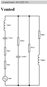
It "might" be possible to gain more insight ec, if we could get the Equivalent Circuit for each driver/design ! For eg, see my screenie from WinISD's helpfile for a vented. I'm not sure if any for TH's have been published though ?
Having said that, simulators must sim these parameters in order to work. So for eg, HR could possibly display these numbers with the symbols in a seperate window. And "maybe" we could interactively change these, or the relevent ones related to this subject. If so, we could see the changes graphically. It "might" then be possible for eg, HR to automatically account for & show this ?
Thanx, got it. The reason i couldn't before, was due to my locking down my normal browser in various ways & methods, for security & privacy reasons. I used a different version that i have for other things, as & when = not often !
I offer some initial observations & input.
Figure 12 - Scatter chart - Linear & Logarithmic trendline look the same, even though the formula details are different ?
In all the graphs, the upper frequency variations/spikes, appear in the same, or almost the same positions ! So this technique only seems to affect the lower f's = good.
It's most likely that some of the larger voicecoils heat up more than others, even with the same/similar power. Which means that the magnets do too. Magnets lose strength when heated, especially Neo ones ! Whether this is significant or not ?
The combination of increased Re & lower BL due to increased heating, = bingo.
It "might" be possible to gain more insight ec, if we could get the Equivalent Circuit for each driver/design ! For eg, see my screenie from WinISD's helpfile for a vented. I'm not sure if any for TH's have been published though ?
Having said that, simulators must sim these parameters in order to work. So for eg, HR could possibly display these numbers with the symbols in a seperate window. And "maybe" we could interactively change these, or the relevent ones related to this subject. If so, we could see the changes graphically. It "might" then be possible for eg, HR to automatically account for & show this ?
Attachments
Figure 12 - Scatter chart - Linear & Logarithmic trendline look the same, even though the formula details are different ?
They look quite different to me, one looks like a straight line and the other looks like a hockey stick shape. And the curved line gets a lot closer to the drivers on the left side of the chart whereas the straight line doesn't get too close to them. The formula is different because the lines are different.
If you mean the curved line doesn't seem to fit the data better than the straight line, it actually does. Looking at the percentage each driver is off the line the curved line has less percentage of variance.
It's most likely that some of the larger voicecoils heat up more than others, even with the same/similar power. Which means that the magnets do too. Magnets lose strength when heated, especially Neo ones ! Whether this is significant or not ?
Actually larger voice coils will have a lot more copper (or aluminum) and a lot more surface area and sometimes even larger wire (smaller gauge) so they should heat up much slower than smaller voice coils.
It "might" be possible to gain more insight ec, if we could get the Equivalent Circuit for each driver/design ! For eg, see my screenie from WinISD's helpfile for a vented. I'm not sure if any for TH's have been published though ?
Having said that, simulators must sim these parameters in order to work. So for eg, HR could possibly display these numbers with the symbols in a seperate window. And "maybe" we could interactively change these, or the relevent ones related to this subject. If so, we could see the changes graphically. It "might" then be possible for eg, HR to automatically account for & show this ?
Any extra info on the voice coils would be a good thing but I'm not sure what you would do with an equivalent circuit. The adjustment method works quite well as it is, it's already automatically done in Hornresp and it's just a single parameter that is adjusted. I'm not saying the method can't be improved but it's already quite simple and very accurate as it is.
I do appreciate your interest but I'm not sure what we could really do with an equivalent circuit and I'm not sure it would be very easy to improve the existing method.
this is great thanks
Hi just a guy,
"Thank You" for the effort. It is highly appreciated.
Regards,
No problem guys, I needed to do it anyway and I like to share. The reason I didn't do this a long time ago was because I knew it was going to be a lot of work. The original generic method took literally no time to develop, I just tried something that seemed like it might work and it worked. This time around I spent about 100 hours developing the new adjustment method and writing it up. I think it's well worth the time spent when looking at the accuracy of the sims in the 30 examples. The image in post 1 was pretty shocking too when LTD02 sent it to me, I hadn't seen an actual overlay before and I was surprised the adjusted curve shape matched so well. Sensitivity is off, but there was no input voltage specified for that particular measurement anyway (I think Ricci blew that driver up before he got all his testing done), and LTD02 just wanted to show the curve shape matched really well.
Originally Posted by just a guy
Actually larger voice coils will have a lot more copper (or aluminum) and a lot more surface area and sometimes even larger wire (smaller gauge) so they should heat up much slower than smaller voice coils.
Slower possibly, but as many of these drivers are capable of kW's of power, they will still reach 100's of degrees in a short time. Sure many have extra cooling features etc, but the magnets will still get Very hot after continued real time use. How much each drivers magnet heats up, obviously depends on factors such as, box/driver design & ambient temp & driven power etc. Whether the increased heat affects the BL in a significant manner ? But we do know it affects Re anyway. I only mention the BL/magnet heat, as an area for further investigation etc.
On closer inspection i see that the lines are slightly different, so sorry for thinking they weren't ! I guess if the left scale was from 5 - 9 i would have noticed straightaway. Talking of Hockey Stick, yours is Nothing like the now infamous Fake data used to try & prove that Co2 is an issue to be concerned about
Global Warming Bombshell | MIT Technology ReviewRe - Equivalent Circuit. If we were able to actually adjust any of the symbols in a sim, we could for eg, then input the extra data that some simmers & test software gives us, into say HR. This might give us even more accurate results ?
As DB said there was an issue with the latest release, i haven't DL'd it yet. But it's GREAT that he has incorporated the feature, with your influence etc. A BIG thanx go to you DB & the others that helped contribute to your compiling & releasing the PDF
Slower possibly, but as many of these drivers are capable of kW's of power, they will still reach 100's of degrees in a short time. Sure many have extra cooling features etc, but the magnets will still get Very hot after continued real time use. How much each drivers magnet heats up, obviously depends on factors such as, box/driver design & ambient temp & driven power etc. Whether the increased heat affects the BL in a significant manner ? But we do know it affects Re anyway. I only mention the BL/magnet heat, as an area for further investigation etc.
Yes, the big coils heat up too, but we can treat heavy power compression in the same way as with regular drivers. Just add some extra Re to see a very general idea of what will happen. But in regards to the drivers tested, I used the "1 watt" measurements for the curve fit. There isn't going to be any power compression at that power level so power compression is not relevant to my testing or adjustment method.
1 watt is in quotes above because he doesn't acutally measure at 1 watt, he uses the closest nominal value so for most of the drivers in the test it was 2V to reflect their close to 4 ohm impedance.
Cool.
I ran the calculation for one of these and found that the new calculated BL actually comes out higher. This appears to be down to the very low Le of this driver, since it has demodulating rings in the motor.
Still, 5" coil and 35mm of winding. I'd call it a large voicecoil.
I might end up putting it in a small sealed box yet, but would prefer a 16Hz-tuned HT monster.
Chris
The link won't work for me and I can't find it in a search either, but I did find the SD21-2000N. I assume they are similar.
First, if it's a pro driver it doesn't fit in this category of very high displacement drivers and it won't be affected by this issue. Also, this driver only has 10 mm xmax, so it's extremely unlikely to be affected by this issue.
Even the TC Pro 5100 which is a very high displacement driver doesn't seem to be affected. There's a heated debate at avs forum about VC sizes, pro drivers vs high displacement drivers, my assertion that this issue is caused by large voice coils and not inductance, and other assorted things.
The fact is that I have no VC info on any of the drivers in the study or any other drivers. That is well outside the scope of this study but it could prove to be very useful information.
At this point I'm assuming that the high displacement drivers have narrow but very long VCs with heavier wire and the pro drivers have very wide but shorter voice coils with thinner wire.
It's clear that pro drivers and high displacement drivers are very different, pro drivers are not affected and high displacement drivers are. A comprehensive study on how the VC and motor are different in these two categories would be a very good thing but I'm not going to do that anytime soon, especially now that I have no internet at home. I might never get around to it, personally I'm satisfied that it's pretty easy which category a driver belongs in by a few clues, most of them can be identified and placed into a category just by looking at them.
Fair enough, thanks for the clarification.
I'd guess the SD21-2000N is similar, too. Mine's the 1800w version.
I'm trying to figure the physics at work here. I suspect that the calculation that produces BL could make assumptions along the way (e.g., about the aspect ratio of the coil) that would throw things out.
I'll do some research and get back to you - I'm on my phone atm.
Chris
I'm trying to figure the physics at work here.
It would be absolutely fantastic if you can show and prove exactly what causes the issue of some drivers not simulating accurately. That seems to be the main point of contention at avs forum and it would be nice if I had a definitive cause, especially if it was something in the published data sheet for a driver that you could point at and say - That's it, this driver affected by this issue. (Or not affected.)
I was happy enough assuming this issue was caused by large coils - some people on avs forum are not convinced and not happy about this assumption at all.
Here's the avs discussion if you are interested. http://www.avsforum.com/forum/155-d...oil-simulation-accuracy-issue-adjustment.html
At this point no one has argued about the method itself or it's accuracy and effectiveness, the discussion has been centered around how to identify affected drivers, inductance vs large coil, and what "large coil" means. I'm probably going to have to change the paper at some point to clarify these issues.
Last edited:
Okay, so BL products...
The product of magnet field strength in the voice coil gap and the length of wire in the magnetic field, in tesla-metres (T·m).
Force = mag field strength (B) x length of wire (L) x current (I).
For some reason, we're getting less force. Impedance and voltage are the same as without modification IIRC, so current remains constant.
Either the magnetic field or effective length of wire have decreased.
If you like, I'll head to the University department and see if I can find anyone that knows more about this.
Ohhh. What if the larger wire gauge used effectively makes a loosely wound solenoid?
That'd give small amounts of field (due to current) leakage, reducing the force applied.
Chris
it would be interesting plotting Le vs X
change of inductance versus position in the gap.
all this stuff* concerns small signal VS large signal models
also another biggie is delta Re as temperature
*departure of predicted models and real life. confirm models with testing under 1V
change of inductance versus position in the gap.
all this stuff* concerns small signal VS large signal models
also another biggie is delta Re as temperature
*departure of predicted models and real life. confirm models with testing under 1V
Last edited:
Okay, so BL products...
The product of magnet field strength in the voice coil gap and the length of wire in the magnetic field, in tesla-metres (T·m).
Force = mag field strength (B) x length of wire (L) x current (I).
For some reason, we're getting less force. Impedance and voltage are the same as without modification IIRC, so current remains constant.
Either the magnetic field or effective length of wire have decreased.
If you like, I'll head to the University department and see if I can find anyone that knows more about this.
Ohhh. What if the larger wire gauge used effectively makes a loosely wound solenoid?
That'd give small amounts of field (due to current) leakage, reducing the force applied.
Chris
Anything you can do would be appreciated. I don't have university contacts so I appreciate your efforts. I would go in armed with some VC example info if you can find it, wire gauge, turns, layers, length, diameter, type (overhung, split, etc), how much of the coil is in the gap, and maybe even wire and former material. At least one example from one of the badly affected drivers and one example of a "normal" driver that is not affected. With no internet at home (not even a cell phone) I can't do this kind of research at this time.
Thanks.
Last edited:
- Status
- This old topic is closed. If you want to reopen this topic, contact a moderator using the "Report Post" button.
- Home
- Loudspeakers
- Subwoofers
- Large Coil Simulation Accuracy Issue and Adjustment