Attached is a first stab at the power amp section. If the JFET/tube cascode diff amp works out ok, I'll use it in other projects. The LEDs I have in mind for the output bias are 70 mA amber Lumileds. I also have my eye on some Osram units that might do the trick.
Attachments
Input stage of power amp has been breadboarded - static voltages & currents are ok, after a massive brain fart blew the thing up (shifted the clip lead with 250V rather than the one connected to DVM in order to measure JFET voltages - predictable result). Pictures and scope plot to follow. Will then breadboard output and hook the two together to exercise a speaker...
Attached find a picture of the input stage breadboard for the power amp pictured a few posts ago. The PVC tube sockets are coming in handy for semi-solderless breadboards. The breadboard is used to check out the hybrid JFET tube differential cascode input/splitter stage. Results will follow.
Attachments
Attached is input output waveforms for the breadboard circuit, showing the inverting half of the cascode diff stage with 1kHz sine wave excitation. I used a 100X probe for both input and output, so the input waveform looks a little noisy. This stage will definitely have enough juice to drive the output stage, with a little left over for feedback. I could get a little more gain with more B+ (250V right now) and higher value load resistors. The PN4393s are showing about 2.7 mS transconductance for 2.5 mA drain current. The breadboard was a proof of concept for the jfet/tube hybrid stage, and so far I'm satisfied.
Attachments
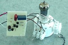
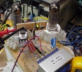
As I promised, I ginned up a breadboard of the output stage of the P-P amp shown here. Important difference - I used an active shunt voltage source instead of LEDs for cathode bias instead of LEDs (sorry, Stuart). The impedance of the active bias circuit is lower than the LEDs, there's no light spillage, and I can dial in whatever bias voltage I choose.
Attached is a photo of my ratty breadboard setup. I used a pair of 6P14P-EVs, with supply voltage set to 330 VDC. Screen bias was set with a zener string (for convenience) at around 250V. I used a baby Edcor 8k transformer I had lying about. First off, I noticed a pretty considerable difference in plate current between the two tubes I picked, so some attempt at finding a matched set out of the 12 tubes I have is in order. I will also need to play with the values on the cathode bias circuit so I can tune in some more bias current.
This effort was a very quick and dirty one to make sure that there were no major gotchas and that the active bias circuit would actually work. Next up is to match a couple of tubes, tune in the bias, and hook up the input stage already breadboarded, using my HV discrete series regulator to supply the input stage B+ and output screen bias. As well as basic gain/power output tests, I want to hit the amp with a square wave input and look at the response of the cathode bias circuit.
Attachments
Attached is a schematic for the active cathode bias circuit. In the picture, it's on the hunk of perf board attached to the breadboard. I may decide to use a current source instead of a resistor to supply the bias current for the LED reference. It may not matter....
Attachments
This project has been sitting around for a bit while i worry about other things (like my job and my unpaid college radio gig). I've been thinking lately and worrying about how the richly endowed (with bias current) stages I have planned will play with the power transformer currently in place...
I have made my decision, and now I am a free man. The power transformer goes, and gets replaced with a custom SMPS. Say good-bye to worries about filament and B+ current, say good-bye to line frequency ripple (the power supply is current mode, so mains frequency ripple cancellation is automatic). I'll pop the hood and check for placement, but there's probably even room for a cage around the power supply. An extra toroid to power the phono preamp will not be necessary, as there will be plenty of DC filament power for all the little tubelings.
The old transformer can be used for a small power amp-only project, maybe using another quad of the 8P14P-EBs.
So, the amp gets gutted except for the sheet metal and output iron, and will be a real wolf in sheep's clothing....
wrenchone said:This project has been sitting around for a bit while i worry about other things (like my job and my unpaid college radio gig). I've been thinking lately and worrying about how the richly endowed (with bias current) stages I have planned will play with the power transformer currently in place...
This reminds me of my Pilot 240 make-over which is still in abeyance. The 240 is a "3-channel stereophonic amplifier/preamplifier".
A wimpy transformer should visit EBay -- I've had issues with Dynaco PAS which can't deliver sufficient filament current for a recent mod...but fitting a beefier one in there is quite a challenge.

I'm reviving this very old thread to ask a question:
Has anyone ever built the 6JK8, dissimilar duo-triode RIAA amp. from posting #20 ?
I'll be asking my tube supplier for some 6GW8's and I see they are letting 6JK8 go for $1,-/ea.
Possibly I should grab a handfull !
rgds,
/tricomp
Has anyone ever built the 6JK8, dissimilar duo-triode RIAA amp. from posting #20 ?
I'll be asking my tube supplier for some 6GW8's and I see they are letting 6JK8 go for $1,-/ea.
Possibly I should grab a handfull !
rgds,
/tricomp
Haven't tried it yet. I have what I think is a more promising approach (with a different tube) I'll be trying first. My concerns at this late date about the original design would be amplified Miller capacitance in the first stage, though the 6JK8 is a low-capacitance tube, as it was intended for RF. First stage Miller is only 0.6pF. A better approach might be a jfet (like the 2SK117) cascoded with a different triode. Having said that, though, the proposed design will probably work as well or better than other approaches that don't bother to address the first stage Miller capacitance.
I think that is the same amp I scored years ago and parted out for the transformers. The PT went into an EL34 based Rt66 copy, although the B+ was a little low it sounded very good. And I used one of the OT's in several EL84 and 6V6 guitar amp projects, sounded OK. The other OT was disassembled as I was into transformer design at the time.
I must admit that your desire to regulate all the tubes with SS components is noteworthy. I like the idea but my experience is that it will work and sound great for a bit but then some transistor will fail and then you have to replace it. Whereas , if you stick with the original circuit, which has worked for 50 or 60 years and was still working when you got the LA234, you could have stock rebuilt it and be using it with no problems. One of the beautiful things about tubes is that they have such a wide operating range and can tolerate so much abuse and still perform. I find that the reliability of SS still below that of tubes. For me i can just change the offending transistor but if you build something for your audio buddy he may not realize that there is a problem until the failed part starts a domino effect and take out a tube or transformer.
OK, thanks for your replies.
I did order a few since the price is so fair it's not going to ruin me completely")
Perhaps they'll be OK for audio-cascode ref. R. Lee Price, IEEE 1954 and M. V. Kiebert, Audio October 1955
(Articles present and available for possible upload if anyone's interested)
I did order a few since the price is so fair it's not going to ruin me completely
Perhaps they'll be OK for audio-cascode ref. R. Lee Price, IEEE 1954 and M. V. Kiebert, Audio October 1955
(Articles present and available for possible upload if anyone's interested)
I have some other ideas re the 6JK8 that might be breadboarded in the near future - a bit of sand, but still a lot of tube, and properly addressing the input stage Miller capacitance issue. Some triode-pentode duals with the pentode stage triode-connected might be better balanced in terms of input stage vs. output stage gain - food for thought, but no spoon-feeding.
- Status
- This old topic is closed. If you want to reopen this topic, contact a moderator using the "Report Post" button.
- Home
- Amplifiers
- Tubes / Valves
- Lafayette LA-234 Amplifier