dice45 said:sreten,
i am not an Englisch native speaker and in German engineering terms the crititical frequency is the frenquency at which the resonance peak, the so-called resonance catastrophe is happening (at zero damping/ infinte Q of course), hence the term "super-critical damping" for positioning the lowest interesting system frequency way above the critical frequency.
So, i don't make sense, huh?
I described exactly what i meant (i re-read my post) and you obviously enjoy to split hairs on technical terms
I do not enjoy that sort of fruitless discussion; i had way more than my share of it already (particularly here@diyAudio). Back to lurking mode. Bye.
Bernhard
Some people just can't take being corrected,
when did damping start meaning tuning ?
") sreten.
sreten.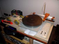
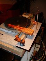
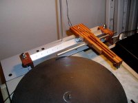
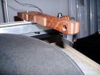
Well done, Peterr!
Looks great, may be a beat heavy? Have you had a chance to measure the lateral resonance fq? What kind of wood is it?
If you want to get its best from this arm, I would suggest to try carbon fiber (damped) arm someday.
My congrats with real world project; not many of speaking here have finished with implementation.
Thank you Livemusic.
It is not the lightest arm but not as heavy as it looks. Wood is much lighter than metal. (the wood I used is Meranti, simply because the DIYmarket sells these strips).
I can't measure the res freq's but according to my calculations it should be about 12Hz vertical and 3Hz horizontal. These are both within the margins that Poul Ladegaard discribes in his original article.
Yesterday I played some non flat and eccentric records and the arm seemed to have no problems with them.
My carbon arm has above 5Hz lateral fq, and compliant Grado felt somehow uncomfortable on it, so it was replaced by D103 - much better. BTW, there was no problem with Grado tracking, the test record's tortue track did not cause any distortion, just I started to feel the sound is somewhat heavy and unnatural with rolled off hights, opposite to "effortless".
I tried five different arm of different design and materials, and the wooden "sandwich" was the worst, in terms, again, clear and effortless sound.
Good luck with your project, I'm sure you have lot of fan with it!
I tried five different arm of different design and materials, and the wooden "sandwich" was the worst, in terms, again, clear and effortless sound.
Good luck with your project, I'm sure you have lot of fan with it!
Peterr,
congrats! good job! BTW, Denon 103 would be a good match with your arm too, i would guess.
oh yes, you had, you just didn't notice. That the arm does not skip grooves does not mean the cartridge is happy with the lateral stylus forces it's cantilever is exposed to.
Months ago, i made experiments with lateral stylus force. I wanted to know if my mechanical linear tracker would perform as expected. I used an Orsonic side force checker and i found that a total mass load of 150+ grams will cause a set of 4 ball bearings (dia 19mm) to jam enough that the side force checker's dial needle went to full stroke. Even if the bearing are running on a knife edge. Which means that the linear tracker's bearing was perfoming far worse than that of a pivoted tonearm.
This experiment lead me to abandoning my mechanical linear tracker project and settle on a Ladegaard linear tracker too.
congrats! good job! BTW, Denon 103 would be a good match with your arm too, i would guess.
Yesterday I played some non flat and eccentric records and the arm seemed to have no problems with them.
oh yes, you had, you just didn't notice. That the arm does not skip grooves does not mean the cartridge is happy with the lateral stylus forces it's cantilever is exposed to.
Months ago, i made experiments with lateral stylus force. I wanted to know if my mechanical linear tracker would perform as expected. I used an Orsonic side force checker and i found that a total mass load of 150+ grams will cause a set of 4 ball bearings (dia 19mm) to jam enough that the side force checker's dial needle went to full stroke. Even if the bearing are running on a knife edge. Which means that the linear tracker's bearing was perfoming far worse than that of a pivoted tonearm.
This experiment lead me to abandoning my mechanical linear tracker project and settle on a Ladegaard linear tracker too.
congrats! good job!
Thank you Dice.oh yes, you had, you just didn't notice. That the arm does not skip grooves does not mean the cartridge is happy with the lateral stylus forces it's cantilever is exposed to.
What do you mean to say? That the arm is too heavy?Peterr,
no, the arm is not necessarily too heavy. But in any case, your stylus will face lateral response forces caused by the need to accelerate the arm and keep the velocity at its current value against stylus2grooove friction (if now the bearing adds friction, the lateral force situation becomes worse and that's why i abandoned my mechanical linear tracker).
Together with cantilever compliance, the resonance frequency is vertically determined by the rotational inertia of the arm wand including cartridge and counterweight. Laterally, the full moving mass applies. I am certain you know that.
Now, the lower you get your total moving mass, the lesser the lateral acceleration-response force will be.
But any passive linear tracker will be atleast 3 times as bad as a pivoted arm in this respect.
Please look if you find my posting concerning the sonic effects of skating misalignment on pivoted arms (maybe the topic is "antiskating adjustment by ear") and then you will see why i stress the necessity of minimizing lateral forces on the stylus.
Moreover, any residual of a lateral force has to push the arm edgewards, not spindlewards and so it would not be the most stupid thing to put a preload pointing spindlewards on a passive linear tracker's sled. Agreed, stylus2groove friction is not constant but with the properly dimensioned preload, the residual force vector atleast pushes the stylus against the inner groove wall. As, TME, ist should be.
Needless to say that such a preload has to be tiny. Think about how to apply it!
Lateral preload
Just give the "rail" very light slope towards the spindle and adjust the platter level in opposite direction. I have noticed no audible difference though...
It is easy if you can level the platter/plinth and armbase separately.Think about how to apply it!
Just give the "rail" very light slope towards the spindle and adjust the platter level in opposite direction. I have noticed no audible difference though...
livemusic and all,
please look for my postings mentioned above. Ia m not sure whether i made them here or @ vinyl-asylum. I can assure you, provided your system is sensitive to µdynamics, you will hear a lot of a difference if your lateral forces are/are not minimized and properly directed.
please look for my postings mentioned above. Ia m not sure whether i made them here or @ vinyl-asylum. I can assure you, provided your system is sensitive to µdynamics, you will hear a lot of a difference if your lateral forces are/are not minimized and properly directed.
Antiscating adjustment for the linear tracker
Bernhard,
After i studied your posts regarding antiscating adjustment, I said to myself: " Makes sence, and worth more accurate tests". First, I adjusted both platter and arm base to perfect horizontal level and listened for several records, trying to compare dynamics on both chanels: indeed, chanels are reproduced unevenly. Then I started to incline by small increments the arm base towards spindel and the platter in opposite direction, to compensate the side force. I must say, the linear tracker has pretty histeric reaction on even tiny discrepance from perfect level: it runs from from side to side accross the blank side record, I use for this purpose, when adjustable leg is turned just 1/20 of turn. That's why I decided to go for separate arm and plater bases in my TT project: I wanted both bases to be levelled independetly. So, I finished with about 0.4 degrees angle between the arm base and platter, as it is seen looking above the record surface towards arm rail. It shall give me around 0.3 gramm of side force applied to the needle (assuming the slider mass is around 100 g including counteweight and cart), in order to compensate the groove reactive force - not a small amount! My measurements are not so accurate, but my ears tell me that the cantilever feels much better with such a preload: image is perfectly centered and more detailed, sound is absolutely unrestricted, and even surface noise surprisingly dropped (!)
Thank you Bernhard for sharing your clever idea!
Dice, thank you for sharing the antiskating idea
I haven't had the time yet but I will certainly try it.
Why do you need to level platter and arm independently? To create a sideforce you have to get your slider off-level. When you change your platter in the opposite direction you are actually changing azimuth. I would think it better to adjust the platter WITH the arm instead of AGAINST it, that way you will create an antiskating force without changing azimuth.
I haven't had the time yet but I will certainly try it.
Livemusic, I don't understand thisIt is easy if you can level the platter/plinth and armbase separately. Just give the "rail" very light slope towards the spindle and adjust the platter level in opposite direction. I have noticed no audible difference though...
Why do you need to level platter and arm independently? To create a sideforce you have to get your slider off-level. When you change your platter in the opposite direction you are actually changing azimuth. I would think it better to adjust the platter WITH the arm instead of AGAINST it, that way you will create an antiskating force without changing azimuth.
Leveling the platter
Peter,
If you would not to incline the platter in opposite direction (relative to horizon), you arm simply run through the record from side to side
So you have to stop it, making it "climb" on the record slope.
Naturally, you shall correct the azimut afterwards, setting the needle normal to the record surface.
Actually the point is simple: you are pushing the cart towards inner groove, in order to compensate its tendency to be pressed against outer groove, because the slider is moved spindlewards by the record, namely by its outer groove.
Haloween's Over...
Hi,
Contrary to what some people seem to believe anti-skating is only applied to classic pivoting tonearms.
Since the direction of support of the tonearm and the direction of force differ, an inside force represented by the formula Fi = µ Wg sin Theta is generated as shown in the picture.
If l=244mm, Theta = 20 degrees, d=14mm, W=2.5gr, and µ =0.4
Tangential tracking arms with a raised carrier rod only show that the initial stiction is too high or/and that the cable dressing is causing too much drag for the cartridge to follow the groove.
Either way, slanting the carrier rod will inevitably result in an azimuth error at all points of armtravel except for the point where it was held at rest and adjusted for.
If Sin Theta equals 0 degrees, as it should, then it follows that no lateral forces can be generated.
IOW the stylus tip will follow a line at the dialed in record revolution.
IOOW, someone's chasing figments of their imagination or is confusing arm assembly stiction with centripetal forces...
Cheers,
Hunting witches in a physical world.
Frank,
You are absolutely right saying the skating force does not exist for a linear tracker. Skating force is a consequence of the offset angle, applied to pivoted arm. Here we are speaking about totally different phenomenon, let’s call it “propulsion force”. Linear tracker’s slider of substantial mass is to be displaced through the record from side to side. Mechanical work has to be performed by a physical force, not by a ghost. No engines here, just side force applied by the outer groove. This force causes cantilever to be shifted from its nominal centered position. Our friend Bernhard and me want to get rid of this force, making the tiny side preload to deal with this work instead.
The air slider friction is very small indeed, but it is still there (think about air flow within the gap). The friction is lower than those of conventional arm gimbals bearing, but the mass is much higher.
Another evil pushing cantilever towards the spindle is a clockwise moment due to friction forces (needle to groove walls) difference between inner and outer grooves. The outer groove is longer, therefore the relative speed and friction is higher on it.
For conventional arm, the skating force is much higher than “propulsion force”, which acts in opposite direction as a sort of weak antiskating device. This is the reason, I guess, why Bernhard recommends adjusting antiskating force a bit lower.
Just plain physics, nothing paranormal involved.
Regards,
Michael
lateral bias
livemusic,
fine that my hints helped you. And IMHO, you grabbed the topic quite well.
Frank and all,
let's call forces laterally applied to the cantilever a lateral bias for the moment, ok? Now, antiskating on a pivoted arm is a special case of that. And sled propulsion force at a linear tracking arm is another special case of it.
Just, how shall the cartridge distiguish between several different kinds of lateral bias? It cannot, the poor thing! It just senses a lateral preload, no matter how the preload was generated, and it loathes it. And answers by punishing -- guess whom? -- by producing bad sonics. Sonics channel2channel dynamically unbalanced, to be particular. Intimidating µdynamics and macrodynamics on left channel and not enough µdynamics (or not at all, depeending on the extent of the imbalance) in the right channel, if the stylus is focusing its pressure on the inner groove wall. And no µdynamics at all on both channels of the pressure focus is on the outer groove wall. No matter how the force is generated.
Abstract: as the friction is music/amplitude depending hence not constant, adjust the lateral bias so that it is putting a force ever-so-slightly bigger on the inner groove wall than on the outer groove wall, just to ensure the lateral bias keeps favoring the inner groove wall. And you will have maximum µdynamics and macrodynamics on both channels.
livemusic again,
If you want to have better resolution for your leveling screws, just try out the following: Make a hollow screw with an outer thread say, MF7x0.75 and an inner threaded hole, say M4. Tap your housing hole for the differential screw at MF7x0.75 again and insert the screw, then insert an M4 screw into the hollow screw's threaded hole. The M4 should be long enough to protrude from the bolt end of the hollow screw.
If you block the hollow screw and turn the inner screw, you have coarse adjustment (tap pitch of M4 is 0.7mm). For fine adjustment you have to keep the inner screw from rotating: turn the hollow screw against inner screw and housing (the pitch of MF7x0.75 is 0.75mm as the name says) then the tap pitches in fact are subtracted and you have a tiny 0.05mm as effective tap pitch per rotation. The neat thing is called "differential screw" and if you buy it as an adjustment device from optical suppliers like Newport or Melles Griot, you pay $$$. But if you buy two tap drills and maybe a tap iron, you can make your own differntial screws for a few cents. Just my
- Status
- This old topic is closed. If you want to reopen this topic, contact a moderator using the "Report Post" button.
- Home
- Source & Line
- Analogue Source
- Ladegaard