darkfenriz said:Is the SMPS modulated with audio signal?
P.S.
Or is it SMPS with two class D amps on secondary working as supply for main linear amplifier??
Study the big picture, it speaks for itself...
Eva said:
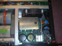
Yes, the SMPS PCB layout almost screams "I'm single ended, not push pull", but it's hard to believe that a flyback of that size could produce 10KW during anything but short intervals.
Also, the 614Khz figure is hard to believe considering the parasitistic inductance of the TO-247 switches and diodes and the gate drive requirements...
Seeing that kind of stuff motivates me anyway
Evita, flyback setup uses 3 parallel connected high voltage 1200V IGBTs and a custom made RM24 Core....and SW frequency is 75Khz...
For this kind of big power, I would use a FullBridge for sure...
The Rail tracking switch is actually IRFP260N driven by TC4420 Mos Driver with floating supply.....The logic is optocoupled with 6N137....to gate drivers....at idle the max Vce across output devices is only +/-7.5VDC, The input to rail Tracking sensing is taken from VAS to match the delay and the Tracking isn't tightly followed, If a full sinewave signal of 15Khz or greater is sensed at input, the amp is muted....
I think Class-D is much more promising than the Class-TD rail Tracking amps...Much less complex...
Hi, EVA,
The SMPS, even it is very powerfull, is a flyback type, with 1 secondary with 1 rectifying diode for each rail. Do you have a tought why they do this and not imply full bridge rectification?
What is your email?
Hi, Kanwar,
I have been looking at the CCT, indeed the items that I wrote yesterday are connected with clipping mechanism, LED display, HF protection. It may be done, but needs carefull redesigning.
Now, before doing anything, the first thing is to remember what Darkfenriz and Mikeks says
The signals are also passed to 70khz 24dB LPF. I think it is connected to the capability of TD modules.
lumanauw said:Hi, Kanwar,
I have been looking at the CCT, indeed the items that I wrote yesterday are connected with clipping mechanism, LED display, HF protection. It may be done, but needs carefull redesigning.
Now, before doing anything, the first thing is to remember what Darkfenriz and Mikeks says
The signals are also passed to 70khz 24dB LPF. I think it is connected to the capability of TD modules.
I think in flyback smps the current is unidirectional and pulsed energy is transferred from primary to secondary only when the Switch is off and therefore it requires only single diode rectification....
Sw-ON||D-OFF & Sw-OFF||D-ON like this....
I already warned you about the CCS and Cascode relation to some integrated clipping and muting functions....There are very few options left now....The LPF is implemented to prevent HF injection into the amp, which would otherwise could cause catastrophic damage...you cannot play with it also...The Clipping detector also helps the MLS switch[load matching switch] to program the power level...
BTW, where are the photos you promised
Play safe
Kanwar
lumanauw said:Hi, EVA,
The SMPS, even it is very powerfull, is a flyback type, with 1 secondary with 1 rectifying diode for each rail. Do you have a tought why they do this and not imply full bridge rectification?
What is your email?
They probably do it that way to reduce part count and to get a simpler circuit. I would not attempt to modify such an amplifier if I was you...
Concerning my email, you already have it since I have received some messages from you from time to time. However, I'm unable to reply because your server always bounces my messages, see:
Subject: Mail Delivery Problems
SMTP error occurred while sending message to following recipient(s)
xxxxxxxxx@xxx.xxxxxxx.xxx.xx
550 5.7.1 Access denied
Eva said:
They probably do it that way to reduce part count and to get a simpler circuit. I would not attempt to modify such an amplifier if I was you...
Evita,
does it means that this simple approach is good or not not good...since it saves lot of components...
From the price of the amp, I doubt if it is about saving component (cost). It makes me think, is it less rectification ripple/diode ripple that they are after? Since in full bridge rectification, the current is coming from 2 secondary windings (each end up in 1 diode). There must be some winding tolerances that makes the voltages in these 2 secondaries cannot be the same, hence more ripple coming if we use full bridge.
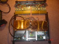
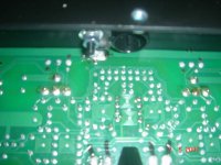
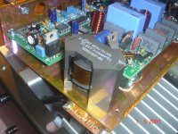
I see that they put snubbers in many points, showing they concern about HF. Even the tracks are strange, I will post picture later. A simple track is made circling around like labyrinth (making L).
I see that they put snubbers in many points, showing they concern about HF. Even the tracks are strange, I will post picture later. A simple track is made circling around like labyrinth (making L).
Mission impossible – or is this a coping matter or do you just want to learn.
This so- called friend is either deaf or he has very inefficient speaker. Did you tell him what active crossover can do for him? Activating the speakers will give him at least 3dB more power if the amp is only driving the bass and the possibility of dedicated amplifier for each driver in the system! Is he listening to music or is he only putting the amplifiers on the bench for sinusoidal test signal? Which pro drivers is this so-called friend using? And I’ll agree - that changing an opamp or a cap won’t do much!
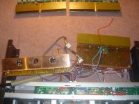
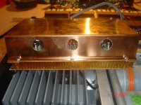
The heatsink system is the way to dissipate a lot of power in light weight and compact fashion. I even think they have a patent – for what it’s worth!
I totally agree – not that I dislike the fP6400 or Lab4000 or LAB2002 or the first LAB2000 from 1991. Have had them all and now I own a fp+10000Q. I have never used them for anything else than low and mid at gigs – why use an amplifier capable of around 3kW power for a horn driver spec around 100W and sensitivity of 110dB/W/m – the smallest iP450 does this job! I personally don’t like the sound of TD amps in the upper range. I would never consider using a pro TD amp at home – I just don’t need this kind of power and the sound of the fans.
Totally agree – nothing more to say. Kenneth and some of the test guys at LAB would too.
Note – hazardous voltage and a lot of capacity. Don’ put the probe wrong.
Take care not disassembling too much like QSC did and then thinking that you can send it back for repair when you can’t assemble it right way again!
Lumannauw:
A friend bought LabGruppen FP6400 power amp. These amps sounds different than so called Hi-End amps. What makes them sound different? (Hi-End amps sound better from his POV). My friend's problem is that he could not find any Hi-End amp that has big enough rating. Too late The owner just cut the main 220V cable head plug of this brand new amp (not even 1 day arrived in his house) just to get these 3 modules out of the amp. Anyone got suggestion what to do? Since this amp is already disassembled (Darkfenriz tells me too late ). Yes, LM4562's are ready to be plugged. But what can be done with the main CCT structure? I often feel that changing caps and opamps are giving better sound, but not in a significant way.
This so- called friend is either deaf or he has very inefficient speaker. Did you tell him what active crossover can do for him? Activating the speakers will give him at least 3dB more power if the amp is only driving the bass and the possibility of dedicated amplifier for each driver in the system! Is he listening to music or is he only putting the amplifiers on the bench for sinusoidal test signal? Which pro drivers is this so-called friend using? And I’ll agree - that changing an opamp or a cap won’t do much!
Eva:
I'm curious about the heatsink arrangement. Could you post more detailed pictures?
The heatsink system is the way to dissipate a lot of power in light weight and compact fashion. I even think they have a patent – for what it’s worth!
Peranders:
Personally I feel that a 6400 W amp at home at 10-100 W is not a particular good choice if you want high fidelity. This amp is made for pumping out kW's day in and day out.
I totally agree – not that I dislike the fP6400 or Lab4000 or LAB2002 or the first LAB2000 from 1991. Have had them all and now I own a fp+10000Q. I have never used them for anything else than low and mid at gigs – why use an amplifier capable of around 3kW power for a horn driver spec around 100W and sensitivity of 110dB/W/m – the smallest iP450 does this job! I personally don’t like the sound of TD amps in the upper range. I would never consider using a pro TD amp at home – I just don’t need this kind of power and the sound of the fans.
Darkfenriz:
I wouldn't really touch it, especially the switching part.
Mikeks:Absolutely nothing! LUMANAUW: Do NOT even THINK of GOING there!
Totally agree – nothing more to say. Kenneth and some of the test guys at LAB would too.
Note – hazardous voltage and a lot of capacity. Don’ put the probe wrong.
Take care not disassembling too much like QSC did and then thinking that you can send it back for repair when you can’t assemble it right way again!
Mission impossible – part 2, Classes and SMPS.
How much power do you need above 15kHz? The amplifier has this circuit to prevent damaging HF drivers and can be disabled at the amp board.
Yes I agree that class D is much simpler, but Class TD has proven its reliability from early on and it handles much better real loads like low impedance, capacitive and inductive loads.
But I would still never dream of use them for HF drivers.
Here you might actually learn something. Kenneth chose the flyback SMPS - exactly because of the way it functions back in the late 1980’s. It works much more like a normal unregulated PSU even though it‘s regulated. Reproducing music tends to be better when no current limiting is interfering both in PSU and amp – do you agree? I have also experienced much better sound when the capacity of the PSU is higher – this must be the fact that music can’t wait for the next energy package to arrive through the transformer whether it’s a ferrite or an iron one.
I can tell you that LAB has sold their SMPS as OEM to the Swedish High-End brand Bladelius some years ago (multi channel amp). Micke is know for his tendency to make very big and powerful supplies. The SMPS is used with both Class AB and Class TD output stages in Lab’s own amplifiers – they don’t sound alike – there is no doubt in my mind which sound the best in the upper frequency range – guess which I prefer.
You are on to something: There is some EMC standard to attend to.
P.S. I’m not a professor, but I know - what I know!
Workhorse:
at idle the max Vce across output devices is only +/-7.5VDC, The input to rail Tracking sensing is taken from VAS to match the delay and the Tracking isn't tightly followed, If a full sinewave signal of 15Khz or greater is sensed at input, the amp is muted....
How much power do you need above 15kHz? The amplifier has this circuit to prevent damaging HF drivers and can be disabled at the amp board.
Yes I agree that class D is much simpler, but Class TD has proven its reliability from early on and it handles much better real loads like low impedance, capacitive and inductive loads.
But I would still never dream of use them for HF drivers.
Workhorse:
For this kind of big power, I would use a FullBridge for sure...
Lumannauw:
I think in flyback smps the current is unidirectional and pulsed energy is transferred from primary to secondary only when the Switch is off and therefore it requires only single diode rectification....
Sw-ON||D-OFF & Sw-OFF||D-ON like this....
Eva:
Yes, the SMPS PCB layout almost screams "I'm single ended, not push pull", but it's hard to believe that a flyback of that size could produce 10KW during anything but short intervals. Seeing that kind of stuff motivates me anyway.
They probably do it that way to reduce part count and to get a simpler circuit. I would not attempt to modify such an amplifier if I was you...
Here you might actually learn something. Kenneth chose the flyback SMPS - exactly because of the way it functions back in the late 1980’s. It works much more like a normal unregulated PSU even though it‘s regulated. Reproducing music tends to be better when no current limiting is interfering both in PSU and amp – do you agree? I have also experienced much better sound when the capacity of the PSU is higher – this must be the fact that music can’t wait for the next energy package to arrive through the transformer whether it’s a ferrite or an iron one.
I can tell you that LAB has sold their SMPS as OEM to the Swedish High-End brand Bladelius some years ago (multi channel amp). Micke is know for his tendency to make very big and powerful supplies. The SMPS is used with both Class AB and Class TD output stages in Lab’s own amplifiers – they don’t sound alike – there is no doubt in my mind which sound the best in the upper frequency range – guess which I prefer.
Lumannauw:
From the price of the amp, I doubt if it is about saving component (cost). It makes me think, is it less rectification ripple/diode ripple that they are after? Since in full bridge rectification, the current is coming from 2 secondary windings (each end up in 1 diode). There must be some winding tolerances that makes the voltages in these 2 secondaries cannot be the same, hence more ripple coming if we use full bridge.
You are on to something: There is some EMC standard to attend to.
P.S. I’m not a professor, but I know - what I know!
Let me clarify some details about these amplifiers... I have repaired a few and I know it VERY well.
First the power supply:
It is a flyback working slightly above 20KHz and its is why it needs a big transformer.
The IGBTs are heavily current limited each cycle. Otherwise it doesn’t sustain the colossal primary current without immediate failure.
The supply is regulated and in the case of the picture posted by Workhorse could sustain only one channel at specified full power 1kHz-4ohm for one or two seconds.
The only advantage I could see in this power supply is that is naturally short circuit proof. I mean: in the short circuit the only components in stress are the output rectifiers, electrolytics and secondary wires. This is inherent to all flyback psu.
About the dissipator:
It is simply an automobile motor thermal radiator. I have seen it for the first time in my car, and second time in an old H/H British amplifier.
About the 15KHz protection:
The amplifier mutes at this frequencies simply because the tracking power supply doesn’t follows the signal… it is not fast enough.( mute or die)
About the modifications in the circuit for better sounding:
No way! The HF noise on regulated rails implies that the amplifier must have a high power supply rejection noise factor. The way they have implemented it, it is not good practice for Hi-Fi. Regular amplifiers will be instable here.
About the patents:
This is the patent: http://www.pat2pdf.org/patents/pat5200711.pdf but the implementation is more like this:
http://www.diyaudio.com/forums/attachment.php?s=&postid=1200773&stamp=1178281024
But the NFB scheme is more like this: http://www.pat2pdf.org/patents/pat4507619.pdf who in my humble opinion is the first UCD patent from Philips.( note the “23” in the schema”).
For other patents, take a look here:
http://www.diyaudio.com/forums/showthread.php?postid=980363#post980363
About the power announced (10Kw)
Let me laugh… The size of buck converter coils on the picture, tells everything. The output power is highly policed. No chance on big concert subbass boxes compared with “traditional monsters” like Crown VZ5000 (near some announced per channel power).
About the power chord for 10KW amplifier: 16amp regular European home appliance.
Thanks all for the input. I'm not the owner, I just follow the owner's will. If you are a car mechanic and someone you know ask you to hit a baseball stick into front glass of his brand new McLaren Mercedes Benz coming out from the dealer (and he will not sue you) will you do that? And you got paid for doing that
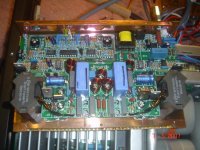
I ended up modifying this amp. The sound now is better (to the owner). He likes modified FP6400 more than his FMAcoustics F50 pairs. I won't tell you what I done exactly, I modify the front end, a bit here, a bit there, because if someday this amp is producing smoke instead of sound, Darkfenriz, Mikeks, EVA, RobertGS, PhaseAccurate all will be laughing at me.
This is when the amp is disassembled. Note that the power cord is cut with scissors by the owner, not me.
Attachments
- Status
- This old topic is closed. If you want to reopen this topic, contact a moderator using the "Report Post" button.
- Home
- Amplifiers
- Solid State
- LabGruppen, what to do?