hello elvee,
sorry to dig out this old thread - i find the microlab very interesting, thank you for sharing!
in my simulation i noticed when setting the current limiter to zero (or any small value around some mA) and having a small load (for example 1k), voltage and current are heavily modulated by ripple.
I suppose this is because the current sensing resistor includes the current absorbed by the regulator itself. or am I doing something wrong?
I think it could make sense to limit the minimum current setting to a higher value?
again thanks for all your project threads, I very much enjoy reading through!
You are right: at low currents, there is a ~10% modulation of the set current:
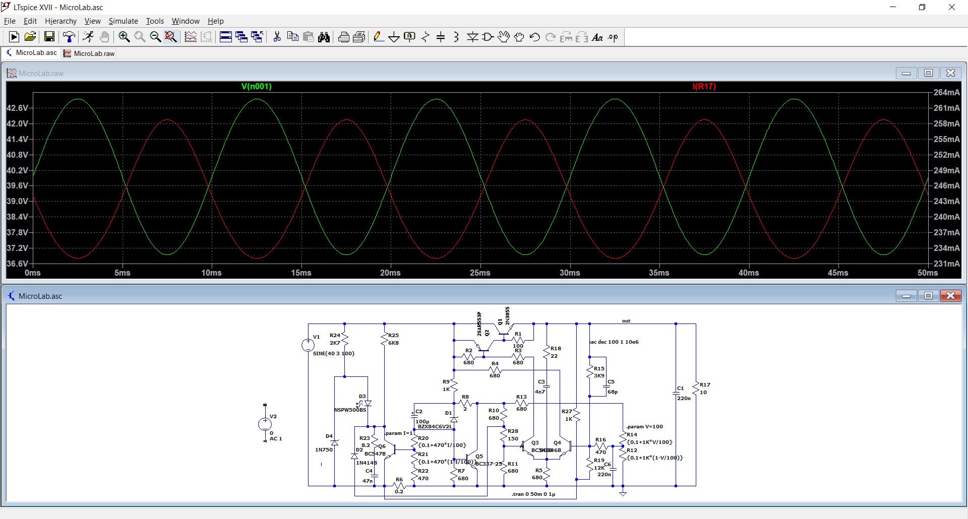
I never noticed it on the actual build, because at low currents the input ripple tends to vanish.
With the sim, the ripple is always 6Vpp, independent of the current drawn.
The funny thing is that the relation between ripple voltage and output ripple is inverse, meaning it is not caused by Early effect in the transistors or something similar.
I will investigate.
Attachments
thanks elvee,
I wanted to build this anyway, but now even more!
my guess was that the regulator draws slightly more current when "opening up" to compensate the ripple, which again modulates the current limiter inversely to the ripple. might be a bit too simplistic...
have a nice evening!
I wanted to build this anyway, but now even more!
my guess was that the regulator draws slightly more current when "opening up" to compensate the ripple, which again modulates the current limiter inversely to the ripple. might be a bit too simplistic...
have a nice evening!
thanks elvee!
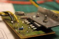
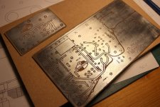
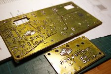
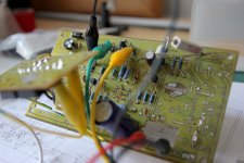
so here is my first try - there still seem to be some problems, eventually related to my rather "graphical" and electrically not so ideal PCB.
I first tried to modify your original circuit
with my somewhat limited knowledge I did the following:
after some doubts to include an IC on such a beautifully reduced discrete circuit I also prepard an auxiliary circuit on the PCB with an LM324 i had lying around for overtemperature shut-down and cooling fan. not installed yet, however.
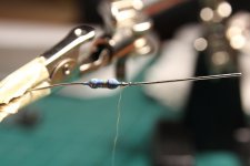
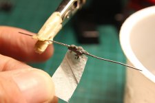
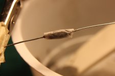
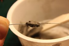
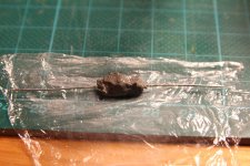
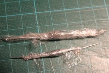
I also took your idea of self-regulating emitter resistors for output transistors from the high-power-circlophone using RG178 wires wound around a resistor and covering them with ceramic tile grout and reinforcing paper. it was necessary to wrap the home-made resistors in vinyl to avoid fast drying of cement, which would make the covering very brittle.
the circuit first did not work as expected and was very sensible to touching of traces or measuring voltages, probably oscillations (?).
after some tweaking (reducing the long traces i made on the PCB for nice potentiometer layout) i got the circuit to work somewhat, but there still are some faults or strange behaviour:
I will try to inspect the circuit with an oscilloscope as next step and make a new and more compact PCB (or even breadboard). this may take some time - no osciloscope here, yet.
any hint or advice is appreciated!
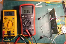
by the way: the output current sharing via DIY PTCs does work beautifully! note the amperemeter photo shows the sharing BEFORE installing the PTCs!
attached some photos for visual enjoyment and my modified ltspice file. I included a varying load to see the regulation transistion.
so here is my first try - there still seem to be some problems, eventually related to my rather "graphical" and electrically not so ideal PCB.
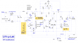
I first tried to modify your original circuit
- for a 20 V transformer that i already have (for max. output around 18-20 V)
- for sharper transistion between voltage and current limiting
- with additional LED indicating voltage regulation, to be able to see the transition between voltage/current regulation
with my somewhat limited knowledge I did the following:
- reduced R9 to provide a similar current to the regulation circuit
- included a Vmax trimmer because reducing R 15 below 3,9 k affected the possible minimum voltage setting
- used a blue LED as D7
- added two 1N4148 to the 4,7 V Z diode (for sharper voltage/amp regulation transition)
after some doubts to include an IC on such a beautifully reduced discrete circuit I also prepard an auxiliary circuit on the PCB with an LM324 i had lying around for overtemperature shut-down and cooling fan. not installed yet, however.
I also took your idea of self-regulating emitter resistors for output transistors from the high-power-circlophone using RG178 wires wound around a resistor and covering them with ceramic tile grout and reinforcing paper. it was necessary to wrap the home-made resistors in vinyl to avoid fast drying of cement, which would make the covering very brittle.
the circuit first did not work as expected and was very sensible to touching of traces or measuring voltages, probably oscillations (?).
after some tweaking (reducing the long traces i made on the PCB for nice potentiometer layout) i got the circuit to work somewhat, but there still are some faults or strange behaviour:
- voltage regulation only starts correctly after slowly increasing input voltage to 24 V. if i start the circuit with 24 V directly the output is about half the desired voltage (9 instead of 18 V) and reacts inversely to the input voltage. when reducing the input to or below 18 V and rising it again the regulation works correctly.
- when setting small current limits the current limit LED lights up even without load and the circuit does not recover after an actual current limit.
I will try to inspect the circuit with an oscilloscope as next step and make a new and more compact PCB (or even breadboard). this may take some time - no osciloscope here, yet.
any hint or advice is appreciated!
by the way: the output current sharing via DIY PTCs does work beautifully! note the amperemeter photo shows the sharing BEFORE installing the PTCs!
attached some photos for visual enjoyment and my modified ltspice file. I included a varying load to see the regulation transistion.
Attachments
-
Models.txt1.8 KB · Views: 42
-
220529-STV_MicroLab.asc12.7 KB · Views: 42
-
 220529-STV_MicroLab.png34.3 KB · Views: 143
 -
 a_IMG_7139.JPG146.8 KB · Views: 125
 -
 b_IMG_7132.JPG161.6 KB · Views: 89
 -
 c_IMG_7140.JPG136.6 KB · Views: 91
 -
 d_IMG_7133.JPG100.4 KB · Views: 85
 -
 e_IMG_7134.JPG94.7 KB · Views: 84
 -
 f_IMG_7135.JPG235 KB · Views: 80
 -
 g_IMG_7141.JPG289.3 KB · Views: 84
 -
 h_IMG_9132.JPG138.1 KB · Views: 106
 -
 i_IMG_8614.JPG265.1 KB · Views: 101
 -
 j_IMG_8624a.jpg350.7 KB · Views: 97
 -
 k_IMG_9111.JPG195 KB · Views: 92
 -
 l_IMG_9131.JPG347.1 KB · Views: 123
Last edited:
Since the sim seems to behave as expected, and I don't see an obvious mechanism for latchup, or latchup-like behaviour (the circuit being so crude and simple) , I think that there is an instability somewhere.
The fact that touching the tracks alters the behaviour is also a hint.
The original circuit was actually built and works (it replaced the crap regulator of a commercial supply), and the mods you made are gentle and should not affect the basic functionality.
Thus, use your oscilloscope to try and locate the hot spot of the oscillations. Then try the usual methods to tame them: base stoppers, small compensation caps or better series RC circuits, etc.
Try to capture and post a picture or two of the culprit(s): it will help narrow down the cause
thanks elvee for your response and help!Try to capture and post a picture or two of the culprit(s)
attached a photo of my PCB with designation of transistors plus circuit diagram.
I suspect it is not ideal to have the power transistors far away from the regulation. my intention was to be independent with mountig the power transistors to the heat sink. I already shortened the wires between the two boards - maybe that's not enough, though.
also the potentiometers are connected with wires. as far as I understand that should not be a problem.

I went to a local maker-space with oscilloscope and I found out the following:
latch up
as described above, my circuit would not start correctly when connected to input voltage of 24 V.output voltage is then about 50% of the desired value (max. 9V instead of 18 V, but independent from voltage setting - always 50 %).
when lowering the input voltage to 18 V and raising it again (or even starting with 18 V) the output voltage is as expected.
furthermore:
when connecting B and C of Q5 just shortly the circuit latches up.
when connecting B and E of Q6 shortly the latchup disappears.
I also found out that whenever touching collector of Q5 with a oscilloscope or multimeter probe the "latchup" would disappear.
apparently the capacitance of the probe + cable releases the latchup. therefore I solved the problem with a 100 nF ceramic cap connected to collector of Q5, see CAP A in the diagram. as far as i see this does not affect regulation or stability of the circuit. probably the cap could be much smaller.
current regulation
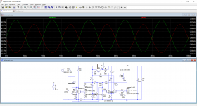
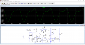
at small current settings, the current regulation LED is always on, even without any load at the output. this is also the case in the original simulation, so probably OK and maybe inherent to the circuit.when checking the circuit with the oscilloscope I found a strong oscillation at collector of Q3 whenever the current regulation is active. the follwing images (1-7) show oscilloscope in AC mode, connected to collector of Q3. description in the images:


in image 7 I connected a 100 nF cap (CAP B) between ground and collector of Q3. that first seemed to tame the oscillation, but the output shows the problem:

oscillation, but at lower frequency.
increasing CAP B to 4,7 uF "solved" the problem ...

.... but I suspect this severely will affect the whole regulation.
(CORRECTION: this was an electrolytic cap, not ceramic as written in the image)
one more image with output when current regulation is active (producing oscillation), without any caps at Q3 (I setting = min, V setting anywhere):

I think I will have to design a new PCB with the complete regulation circuit gathered on one board, also avoiding those long beautifully sloped traces ... mainly avoiding long distances between Q3 and output transistor circuit. any advice?
anyhow, until now this was a great learning experience, thanks!
Last edited:
I don't think your problems are due to the layout (mostly): it could have been better, but due to the current-control mode of the ballast and the inherent 680 ohm stoppers, this topology is extremely robust regarding those aspects (unless you use RF transistors, but it does not seem to be the case).
This means that you have to look elsewhere, and first separate the problems: apparently, you have issues with the current limiter, even when it should play no role.
You should have the voltage regulator working on its own before going further. This means that you should disable the current regulation, by lifting D2 for example.
Does it solve the problems (in voltage mode only, obviously)?
If it doesn't, look at the compensation components: C5, C3, R18, C1, C6? Are they OK? You can sometimes confuse decimals, etc. Are they actually, physically connected where they should? If everything looks OK, try tweaking (gently) the values and observe the results. This should preferably be done with an oscilloscope.
You can also try to massively increase the value of C1, but it is brute force, and should not be used in the final implementation, as the stored energy could cause damages before the limitation kicks in.
Try all of the above, and report. Depending on the results, we will decide what are the next steps to be taken
thank you very much, elvee. really appreciate your insightful help!we will decide what are the next steps
I will do as you suggested and post the results.
thanks YashN, that should indeed be possible.you should be able to have your DSO dump its oscilloscope screen contents to JPGs or BMP files for better image sharing
it is not my oscilloscope (public maker space) and i am just starting to get used to it.
I'll try it next time, also for the sake of smaller file size.
just a small update for anyone interested and for documentation - sorry progress takes so long. i have to few time for the hobby at the moment!
@Elvee, as you suggested I disconnected current regulation by lifting D2.
oscillation still present, amount depends on the measurement point:


this leads me to the assumption that i do have a layout problem - presumably parallel cable connections highlighted in green on the scheme.
by very much reducing output current the oscillation disappears:

when reconnecting the current limiter and driving the circuit into current limiting the oscillation appears at varying frequencies. but again i suspect the regulation cannot work stable with my layout.

by the way: saving screenshots as you suggested, @YashN, does not work or I am doing something wrong. oscilloscope confirms but there is nothing on the USB stick. thus the photos!
I will spend some more time testing.
regards and thanks again!
@Elvee, as you suggested I disconnected current regulation by lifting D2.
oscillation still present, amount depends on the measurement point:
this leads me to the assumption that i do have a layout problem - presumably parallel cable connections highlighted in green on the scheme.
by very much reducing output current the oscillation disappears:
when reconnecting the current limiter and driving the circuit into current limiting the oscillation appears at varying frequencies. but again i suspect the regulation cannot work stable with my layout.
by the way: saving screenshots as you suggested, @YashN, does not work or I am doing something wrong. oscilloscope confirms but there is nothing on the USB stick. thus the photos!
I will spend some more time testing.
regards and thanks again!
This is extremely puzzling. Anyway, the wiring to the power transistors should not matter very much, unless there is a problem elsewhere, and running the cables parallel, in close proximity is the right way to do it, to minimize the loop area.
From the pics, I see that the input 4700µ is directly on the board, yet a relatively large amplitude seems present on TP3, which is illogical.
Could you take a measurement on the emitter of Q2?
Here are some tests you can try:
-connect a ~1nF capacitor between B and C of Q2
-connect a ~1nF capacitor between B and C of Q3
-parallel R1 with 22nF
-parallel R6 with a 1µF ceramic.
Make all the tests one by one, and observe the result
Just to leave no stone unturned, measure the collector of Q5: even if the rest is oscillating like mad, it should remain dead quiet
thank you very much, @Elvee
I still suspect that I may just have made a very silly mistake and thus appreciate your patience even more!
considering the voltage divider R2+R3 this should be around 1,5 V peak-peak, is this what you mean?
anyhow, I will follow your proposals and report back.
regards and have a nice day!
I still suspect that I may just have made a very silly mistake and thus appreciate your patience even more!
I got a 3 V peak-peak oscillation at test point 4 and 1,92 V at test point 3.yet a relatively large amplitude seems present on TP3, which is illogical.
considering the voltage divider R2+R3 this should be around 1,5 V peak-peak, is this what you mean?
anyhow, I will follow your proposals and report back.
regards and have a nice day!
quick update and thanks again @Elvee :
I also tried to modify the simulation to get it to oscillate. the only way was to add inductance to the current sensing resistor.
I will change the wirewound high inductance current sensing resistor to a low inductance metal film type and check for oscillations - maybe that was the cause of this all!
I also found out the "latchup" described in post #28 disappears if R9 is increased back to 1 kOhm as in the original circuit.
I found out because Q5 got quite warm, so I decreased the current through it by increasing R9.
my initial intention in the simulation was to optimize current regulation by keeping currents through Q5 similar to the active current limit current through Q6.
alternatively the current of Q6 could be lowered by increasing R24/R25. tested this in the simulation (works) and in the built circuit (regulation below 100 mA seems difficult with high voltages, but that is perfeclty ok for my application).
have a nice sunday!
- 0,47 uF ceramic parallel to R6 (current sensing resistor) tamed oscillation
- 1 nF between B+C of Q2 tamed oscillation
- 1 nF between B+C of Q3 tamed oscillation
- 22 nF parallel to R1 did not change oscillation
I also tried to modify the simulation to get it to oscillate. the only way was to add inductance to the current sensing resistor.
I will change the wirewound high inductance current sensing resistor to a low inductance metal film type and check for oscillations - maybe that was the cause of this all!
I also found out the "latchup" described in post #28 disappears if R9 is increased back to 1 kOhm as in the original circuit.
I found out because Q5 got quite warm, so I decreased the current through it by increasing R9.
my initial intention in the simulation was to optimize current regulation by keeping currents through Q5 similar to the active current limit current through Q6.
alternatively the current of Q6 could be lowered by increasing R24/R25. tested this in the simulation (works) and in the built circuit (regulation below 100 mA seems difficult with high voltages, but that is perfeclty ok for my application).
have a nice sunday!
Last edited:
Good. This means that the main issue was the inductivity of R6. Adding 0.47µF or 1µF is not going to alter the protection, so it is the way to go. That said, you should make extensive tests with various loads, under various conditions to make sure all the problems are effectively cleared.
If you still encounter marginal problems, try the other fixes (but the final circuit should use much less aggressive values: 1nF is for testing the concept)
If you still encounter marginal problems, try the other fixes (but the final circuit should use much less aggressive values: 1nF is for testing the concept)
No worries, your photos are still quite readable, the USB pic save is a convenience... when it worksby the way: saving screenshots as you suggested, @YashN, does not work or I am doing something wrong. oscilloscope confirms but there is nothing on the USB stick. thus the photos!

after testing with the scope with different loads and all possible settings I can confirm: using a low-inductance metal film resistor for current sensing solved all oscillation problems!That said, you should make extensive tests with various loads, under various conditions to make sure all the problems are effectively cleared.
no cap necessary,
cheers and thanks!
- Home
- Amplifiers
- Power Supplies
- Lab supply on a shoestring