I've built a couple of the enclosures using the plans from post #270.
Did you made some modification on original plan?
Do you think that the same enclosure could work for the infinity 1260w?
I did sim a box for the infinity 1260W but not have build it yet, to busy
find a classic car, get wood with the bike is problematic.
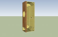
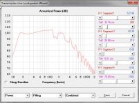
The box is simmed without damping with low pass filter selected.
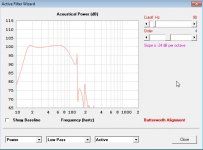
And one without low pass filter and damping added.
The jet liking port is separated simmed and after that exported to the design hornresp can do not both in one go.
nice looking box you have here.
find a classic car, get wood with the bike is problematic.
The box is simmed without damping with low pass filter selected.
And one without low pass filter and damping added.
The jet liking port is separated simmed and after that exported to the design hornresp can do not both in one go.
nice looking box you have here.
Attachments
Last edited:
Thanks for answer!
NWCgrad's enclosure is very nice and compact to be a trasmission line subwoofer!
It seems to me that both driver are not too off.
They are quite similar to Lab 12 and maybe 1260w a bit more.
I was thinking to both as lab's 12 cheaper replacements...

NWCgrad's enclosure is very nice and compact to be a trasmission line subwoofer!
It seems to me that both driver are not too off.
They are quite similar to Lab 12 and maybe 1260w a bit more.
I was thinking to both as lab's 12 cheaper replacements...
Last edited:
Took me some time but here's a pic. Don't mind all the wires, there's soon to be some trim pieces hiding the wire and the battery.Ahh the BD1000, good times, good times.
Those amps were sooooooo good, used to sell them.
pics?
An externally hosted image should be here but it was not working when we last tested it.
Took me some time but here's a pic. Don't mind all the wires, there's soon to be some trim pieces hiding the wire and the battery.
Looks like you've got enough space back there for 3 of these, haha!
I haven't made any sawdust yet but I ran the sims and 'sketched' it up for an old pair of JL 10's I've had sitting around for many years
And yeah I even took an evening to draw the curved grills & drivers components as separate pieces and assemble them as groups
And yeah I even took an evening to draw the curved grills & drivers components as separate pieces and assemble them as groups
An externally hosted image should be here but it was not working when we last tested it.
An externally hosted image should be here but it was not working when we last tested it.
An externally hosted image should be here but it was not working when we last tested it.
An externally hosted image should be here but it was not working when we last tested it.
An externally hosted image should be here but it was not working when we last tested it.
Last edited:
How come you sim'd CON instead of PAR?
Cause I wasn't paying enough attention, I just changed it and it made a difference of 11.47 cubic inches (0.188ltr) and the sim response didn't change so I'm not worried about it. Thanks for pointing it out though
Tundra,
Great looking 3d model there!
How do you display the 3d model and HR sim tilted on same screen like that?
Can't wait to hear your listening impressions and measurements.
Great looking 3d model there!
How do you display the 3d model and HR sim tilted on same screen like that?
Can't wait to hear your listening impressions and measurements.
An externally hosted image should be here but it was not working when we last tested it.
How do you display the 3d model and HR sim tilted on same screen like that?
An externally hosted image should be here but it was not working when we last tested it.
That does look cool!
Tundra,
Great looking 3d model there!
How do you display the 3d model and HR sim tilted on same screen like that?
Thanks! The model view is a 2d export from sketchup, the HR was a screen capture. I opened the model pic in photoshop and added the screen capture with the HR sim as a new layer, cropped it and then used the transform-skew tool to give it a 3d look
Thank you everyone for a very nice design. Once again a lot of careful work has gone into this to yied a wonderful design.
I have a question. In post 308 (pg 31). thejessman shows a picture of his nice build. The build includes bracing between most internal parts. If bracing was used throughout, should the width of the cabinet be increased by the thickness of the bracing?
Thanksshows a picture of his nice build. The build includes bracing between most internal parts. If bracing was used throughout, should the width of the cabinet be increased by the thickness of the bracing?
Thanks
Hi rocksteady40,
Post #334: "...In post 308 (pg 31). thejessman shows a picture of his nice build. The build includes bracing between most internal parts. If bracing was used throughout, should the width of the cabinet be increased by the thickness of the bracing?"
Short answer: Yes, but not necessary, especially if you use big cutouts in the braces.
I have simulated quite a few of these cabinets, and the thickness of one layer of bracing does not change the simulations very much. I recommend you fire up Hornresp, and give it a try (see the compilation of design elements by NWCgrad in Post #270/273). In this enclosure I squeezed the cross-sectional areas to what I consider the minimum necessary, so don't use 1.5" bracing.")
Regards,
Post #334: "...In post 308 (pg 31). thejessman shows a picture of his nice build. The build includes bracing between most internal parts. If bracing was used throughout, should the width of the cabinet be increased by the thickness of the bracing?"
Short answer: Yes, but not necessary, especially if you use big cutouts in the braces.
I have simulated quite a few of these cabinets, and the thickness of one layer of bracing does not change the simulations very much. I recommend you fire up Hornresp, and give it a try (see the compilation of design elements by NWCgrad in Post #270/273). In this enclosure I squeezed the cross-sectional areas to what I consider the minimum necessary, so don't use 1.5" bracing.
Regards,
Dear audio mates,
I'm really attracted by this design!
OD-MT-TL let me imagine a transmission line with limitate dimensions, where I can put my Infinity Ref. 1260w.
The purpose is to make a sub for music listening.
I never used Hornresp but now I perceive its power. Having such an instrument for free is amazing, in the hope to obtain a good correlation with measured data. I enjoyed a lot in using it, in these days, especially the "Speaker wizard". But I'm a novice on that and I don't try to add stuffing nor implement electronic filters.
I attach a result I can suppose good. It does not reach an astonishing extension in low frequencies, but features limitate GD, low overall volume (77 liters), and a not too narrow (178 cm2) exit port.
Regarding the folding, I never do that, but bjorno suggestions let me think about it.
I imagine a folded enclosure (like post #273) with a inner depth of 35 cm (to include the speaker). We should have:
S1 = S2 = 580 cm2. So 580/33 (35 - 2cm bracing) = 17.5 cm for the first segment, long 65 cm, going from the back to the middle of the speaker.
S3 = 178 cm2. So 178/33 = 5.4 cm Hence the second segment starts from the middle of the speaker (width 17.5 cm) and extends for 67 cm to reach 5.4 cm.
The third (last) segment is a constant height (5.4 cm) with a leght of 76 cm.
This port, although not too narrow, may have a final flare to improve the result.
I hope some more experienced members can comment, correct, suggest some improvements.
Kind Regards
Fabrizio
Attachments
Greets!
Your sim is somewhat different than the OD-MT-TL and can be simplified to a simple one fold TQWT plus ideally should be tuned to Fs or a little lower, making it a little larger with output to 20 Hz where it will need a hi-pass to protect it for some music, movie LFE:
GM
Your sim is somewhat different than the OD-MT-TL and can be simplified to a simple one fold TQWT plus ideally should be tuned to Fs or a little lower, making it a little larger with output to 20 Hz where it will need a hi-pass to protect it for some music, movie LFE:
GM
Attachments
GM, thank You very much for Your suggestions!
What do You mean with "Your sim is somewhat different than the OD-MT-TL" ?
I think Your simpler shape has a comparable construction complexity, isn't it?
I agree that this will require a good "rumble filter"
I also agree that the enclosure should enhance the emission at low frequencies, possibly lower than Fs. Mine do not.
Your simulation is immediately more efficient in that!
Anyway 106 litres of Volume brings some unwanted issues:
1) worst impulse response and group delay (Is there some method to fight that?)
2) quite big enclosure
Music listening, differently from film watching, possibly requires fast impulse response (a lot of audiophiles prefer a sealed enclosure, although with EQ correction).
My simulation features also a great defect in the "acoustical impedance" (peak over 500 ohm) while Yours is under 300. I don't well understand what does it means. Does the the speaker suffer more loading when acoustical impedence is high?
I attach an "intermediate volume" simulation where I limitate the volume to around 90 litres and where acustical impedance is now under control. There is deliberately a peak around 30Hz that should be smoothed with filling...
What do You think?
Regards,
Fab
Attachments
Hello I would like to build sub woofer from post 270.
I have access to CNC cutter and I would like to be able to modify design to CNC need.
Does any one have .DWG (auto cad files) or vector files (.PDF, .AI ir .EPS) for drawings from post 270?
I would adjust them and share back to community for any one to use.
Please let me know.
I have access to CNC cutter and I would like to be able to modify design to CNC need.
Does any one have .DWG (auto cad files) or vector files (.PDF, .AI ir .EPS) for drawings from post 270?
I would adjust them and share back to community for any one to use.
Please let me know.
- Status
- This old topic is closed. If you want to reopen this topic, contact a moderator using the "Report Post" button.
- Home
- Loudspeakers
- Subwoofers
- Lab 12 Based Offset Driver - Mass Loaded - Transmission Line (OD-ML-TL) Design by Bj