Hi, anyone build the Kumisa III PreAmp?
How it sound? Better than a global feedback preamp?
I will work in a PCB for this preamp, and I like some opinions before.
How it sound? Better than a global feedback preamp?
I will work in a PCB for this preamp, and I like some opinions before.
An externally hosted image should be here but it was not working when we last tested it.
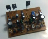
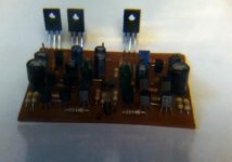
Hi, the amp sound very good.
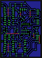
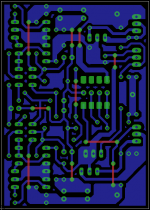
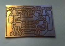
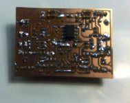
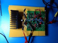
This is the 1st PCB prototype, what do you think?
Some resistor are in the botton side. Links are only GND or +/-Vcc.
Size 5cm x 7cm, DC servo included.
This is the 1st PCB prototype, what do you think?
Some resistor are in the botton side. Links are only GND or +/-Vcc.
Size 5cm x 7cm, DC servo included.
Attachments
I see I'm the only one following this thread, but I'll post anyway 
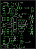
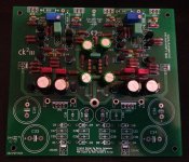
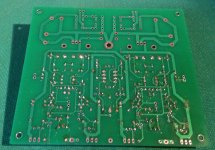
Work in progress of my second CK2III board, which will be adapted to EF output stage using the original Toshiba drivers and Rohm output transistors (the latter are sounding great in the CFP stage of my other CK2).
ATM I'm awaiting delivery of the psu and a batch of Rohm 2SB1186A/2SD1763A from which I'll match a quad.
Attachments
No denigration of Cavalli or Kan but if you get a working Kumisa3 preamp board going, I am sort of interested.
I understand. I have no plans to etch a pcb of the original schematic, at least not in the near future. I will post about my impression of using the original drivers/output transistors on the CK2III pcb (with just some cable extensions) and after comparison, I'll move on to different projects.
Then, if and only if the CK2III (either version) will still sound better to my ears than the other amps on my to build list, I can go as far as making the original pcb, the main differences being the bipolar input stage and the configuration of the servo opamp (I think the CK mod is better on this regard, but I'm open to discussion).
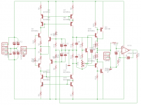
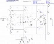
After a couple months banging heads here and there, my mockup is finally working. The servo is exactly as in the CK2III, some values set a gain of about 4.3x, and the output stage is EF, with drivers biased differently than the kumisaIII (in a more stable way IMO), as used by Aloia in some Arcam amp.
+-15V are absolutely fine and the simulated performance is better than the kumisaIII with default values and WAY better than the CK2III.
Attached the schematic and working setup (i'm probing left channel DC offset). The breadboard, although I didn't do it myself, is not difficult to make. Bias is a bit too high for the heatsink used, in my simulations, a value around 550R should be a good compromise.
I have yet to run the full voltages/currents measurements, and finding ideal bias point, before checking it with the scope. Please note again that the bias in the schematic is too high and would cause 14-15W of dissipation.
I can post variuos ltspice graphs if there is interest.
Lastly, I'm considering replacing the BC550/560C for VAS and drivers with 2SA1015Y/2SC1815Y of which I have enough matched with about 200 hfe. They should be more linear at the pretty high currents used in my circuit.
I had the drivers used in the kumisaIII, but the PNP complements after some testing showed a weird behaviour (the beta lowered from my initial testings) and I believe they could have been fakes, so I plan to go with the above pair.
Attachments
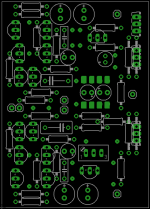
Yesterday I resolved an issue with the right channel (likely a cold joint around the VBE where the pads were consumed due to several resoldering). Now the amp is working as it should.
Bias is set to about 90mA per output transistor, which corresponds to about 700R in my last schematic. I'm now back using trimpots, and fine tuning them measuring between R101 and R102 in my schematic. This way the heatsink should stay at around 60°C. I'm not confortable to super-hot amplifiers, especially where that much power is not needed (I dont have nor plan to buy an Ortho).
I have to say that at this power level, the bias is not very stable and would require a diode/or the VBE transistors to be mounted onto the heatsink. I will do this tomorrow, together with the final assembly (hoping that the sigma22 is allright, because I haven't tested it).
Today I did signal testing with my generator and analog scope (50hz, 1khz, 10khz, 20khz sine, 1khz triang, 1khz and 10khz square). Everything seems to be just fine, both channels. I was worried about the right ch since the issue I had before with the bias.
I can say that the burn-in was done during bias/heat testing all this week, the amp must have been on 20-30 hours.
I will update this thread tomorrow or sunday with some pr0n.
- Status
- This old topic is closed. If you want to reopen this topic, contact a moderator using the "Report Post" button.
- Home
- Amplifiers
- Headphone Systems
- Kumisa III Amp