KT88SE low DCR power supply mod
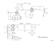
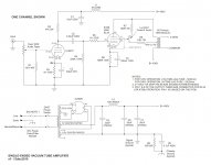
Here is the circuit that I am running now on my KT88.
I rebiased the 6N1P for more current. After listening to both for quite a while, I can't really tell any difference in LED or conventional RC bias in this circuit. I do believe I can tell a difference in clarity due to the increased current though.
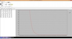
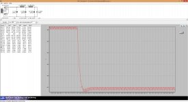
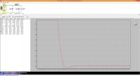
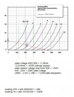
The power supply has been modified to a lowish DCR version. I have attached the PSUD2 graphs that show the power supply settling time for the modified vs. the original configuration. Again, I'm not sure if the major difference is the low DCR and settling time or the fact that the B+ is now 440V instead of 400V due to the use of the damper diodes.
Even without changing the choke configuration, the settling time is much better using the damper diodes. Also the B+ comes up to ~440V. As you can see, there is not much difference in using the damper diodes or just using a 5AR4 in place of the 5U4GB. The 6CL3 damper diodes will be tolerant of the series limiting resistance of the power transformer. A 5AR4 may not. The power transformer itself does not have the resistance necessary to safely run the 5AR4 in spec. In this circuit, the damper diodes are just barely idling and should last a very long time.
So, basically, the easiest way to increase the performance of this amp is to change the 6N1P bias, and change the 5U4GB to (2) 6CL3/6CK3 damper diodes. To power the heaters for the 6CL3, use a Schottky bridge rectifier circuit for about 6VDC. The center tap for the 5V winding in this case is just capped off and left unused.
As I mentioned before, I am still working on the increased hum issuing caused by changing the choke configuration. If you choose to just change the rectifier to the 6CL3 configuration, hum will not be an issue.
I welcome any comments or questions.
Scott
edit: I removed the 1.5K resistor that is used for UL mode. I moved the 100R resistor directly to the screen socket terminal. The triode/UL switch now just switches the screen connection between the UL tap and the plate. This is how it should have been from the beginning. My mistake. Although there were no complaints from anyone, and apparently it works as is, you might want to make the change. I also added a 1K grid stopper to the 6N1P.
Here is the circuit that I am running now on my KT88.
I rebiased the 6N1P for more current. After listening to both for quite a while, I can't really tell any difference in LED or conventional RC bias in this circuit. I do believe I can tell a difference in clarity due to the increased current though.
The power supply has been modified to a lowish DCR version. I have attached the PSUD2 graphs that show the power supply settling time for the modified vs. the original configuration. Again, I'm not sure if the major difference is the low DCR and settling time or the fact that the B+ is now 440V instead of 400V due to the use of the damper diodes.
Even without changing the choke configuration, the settling time is much better using the damper diodes. Also the B+ comes up to ~440V. As you can see, there is not much difference in using the damper diodes or just using a 5AR4 in place of the 5U4GB. The 6CL3 damper diodes will be tolerant of the series limiting resistance of the power transformer. A 5AR4 may not. The power transformer itself does not have the resistance necessary to safely run the 5AR4 in spec. In this circuit, the damper diodes are just barely idling and should last a very long time.
So, basically, the easiest way to increase the performance of this amp is to change the 6N1P bias, and change the 5U4GB to (2) 6CL3/6CK3 damper diodes. To power the heaters for the 6CL3, use a Schottky bridge rectifier circuit for about 6VDC. The center tap for the 5V winding in this case is just capped off and left unused.
As I mentioned before, I am still working on the increased hum issuing caused by changing the choke configuration. If you choose to just change the rectifier to the 6CL3 configuration, hum will not be an issue.
I welcome any comments or questions.
Scott
edit: I removed the 1.5K resistor that is used for UL mode. I moved the 100R resistor directly to the screen socket terminal. The triode/UL switch now just switches the screen connection between the UL tap and the plate. This is how it should have been from the beginning. My mistake. Although there were no complaints from anyone, and apparently it works as is, you might want to make the change. I also added a 1K grid stopper to the 6N1P.
Attachments

Last edited:
+edit: I removed the 1.5K resistor that is used for UL mode. I moved the 100R resistor directly to the screen socket terminal. The triode/UL switch now just switches the screen connection between the UL tap and the plate. This is how it should have been from the beginning. My mistake. Although there were no complaints from anyone, and apparently it works as is, you might want to make the change. I also added a 1K grid stopper to the 6N1P.
So the change is basically changing the 1.5k resistor with a 100ohm one? Could you elaborate on it, in which sense it affect the performance this resistor's value?
I can't remember if I fitted the stopping grid resistor on the 6N1P, but sure I thought "why didn't he fitted it?"

I can see there are 3 inductors in the schematic now, I can't remember when did you add one. have you talked about it in another post I've missed?
Best regards!
Attachments
So the change is basically changing the 1.5k resistor with a 100ohm one?
1. Remove the existing 100R resistor from pin 3 (plate) of the KT88. Connect the blue wire back to pin 3 directly.
2. Remove the orange wire from pin 4 (screen) of the KT88. Connect the 100R resistor directly to pin 4. Connect the orange wire you removed to the other end of the resistor.
3. Remove the 1.5K resistor from the toggle switch and the red wire. Connect the red wire directly to the toggle switch.
Could you elaborate on it, in which sense it affect the performance this resistor's value?
The original 1.5K was a recommendation when I was putting the kit together. Information that I have read since then indicates that the UL screen stopper resistor should be as small as possible to perform its function of suppressing oscillation. Many designs, including the original Abdellah design do not even use one. A larger resistor "may" even introduce non-linearities in the way that the screen tracks the plate in UL mode. The 100R resistor, as a stopper resistor, works better if soldered directly to the socket pin.
Obviously the way the amp was originally wired does not cause any problems. Maybe because no one who built one lives next door to a radio transmitter?
Modify one channel, and then listen to both. I doubt that you will tell any difference.
I can see there are 3 inductors in the schematic now, I can't remember when did you add one. have you talked about it in another post I've missed?
Yes, in the same post that you just quoted.
Best regards!
Attachments
As I mentioned before, I am still working on the increased hum issuing caused by changing the choke configuration. If you choose to just change the rectifier to the 6CL3 configuration, hum will not be an issue.
Is this noise issue resolved? (ref post #241)
No, I have not had much time to work on that lately. I have not given up though. The hum really is barely audible.
For reference, a friend of mine has a pair of stock Klipsch Forte speakers. They are spec'd as 98dB @ 1W/1 meter. I'm sure they are not quite that sensitive in the real world. The hum becomes audible at about 1 ft from the speaker.
For reference, a friend of mine has a pair of stock Klipsch Forte speakers. They are spec'd as 98dB @ 1W/1 meter. I'm sure they are not quite that sensitive in the real world. The hum becomes audible at about 1 ft from the speaker.
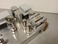
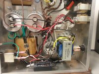
I don't think I want to attempt the choke reconfiguration yet, especially after seeing the creative structural work in Scott's photo. However, I'm building a list of parts I'm hoping to source here (limited options for me) to rebias the 6N1P.
I see, I'll probably do the same as Scott and move the 5H chokes up to the front and make a second hole for the 6CL3. ... Wish I had a drill press!
1x 470uF 35V
2x 100uF 25V
2x 150R (1/2W)
2x 220k (2W)
2x 6CL3 (Plus spare)
2x Novar Socket (Is this right?)
4x SB530 Schottky
On another note, I just "fixed" the triode/UL switch. No audible difference for me.
Concerning the triode/UL "fix", I couldn't tell any difference either. I just changed it just to align with what seems to be more standard practice, although that's not too standard either as you see amps with different values and many UL amps with no resistor on the screen at all.
Yeah, that choke on top is kind of ugly. I had some of the material left over from the last amp I built the cage for.
So do you have 1K resistors already? You understand that you connect a 1K and a 150R in series to make a 1K15 (1150 ohm) resistor, then you place those two resistors in parallel with the existing 1K to get the 535R value.
Yes, Novar socket. The most readily available seem to be the 2-piece Chinese ceramic version. If you have trouble finding these send me a PM.
Yes, if you decide to make the change to the 6CL3 (or 6CK3) do buy extras. I bought quite a few and as luck would have it, one of the two I first picked out of the box was weak. The symptom was low voltage.
A knockout punch for 3/4" conduit works perfectly for the Chinese ceramic Novar sockets if that what you intend to order. The 3/4" conduit punch actual hole size is about 1-1/8".
Last edited:
Hi Scott,
I was inside the amp just now and I think I injured the 6N1P when removing it, because it doesn't seem to heat up anymore and the amp is completely silent. I shut it off after the rectifier arced once and don't want to turn it on until I can get some time to diagnose further.
I don't have a spare unfortunately, so we shall see once I get one. Not sure what else to test at this point.
I see you want the B+. Can I get that with just the rectifier plugged in? I don't have the nice instructions anymore. Good place to measure? I'll have to find that bleeder resistor too
EDIT: 238VAC at the wall, 409V B+.
Thanks for catching my mistake with the resistor. 130 ohms is quite a bit off from 535.
On a side note: The grid stopper is independent of the re-biasing, correct?
Last edited:
Well that is not good. Sorry.
edited after crossing posts: actually that is good that your 6N1P is ok.
Is the B+ reading under no load?
Yes, the 6N1P stopper resistor is a completely separate issue. Although there is no current problem without it, it's just standard practice. I probably should have included it with the kit.
edited after crossing posts: actually that is good that your 6N1P is ok.
Is the B+ reading under no load?
Yes, the 6N1P stopper resistor is a completely separate issue. Although there is no current problem without it, it's just standard practice. I probably should have included it with the kit.
Last edited:
I'm usually so meticulous with my soldering, which made me check everything except the wires to the heater on the 6N1P.
Correct, the B+ reading was without load. You'll have to forgive me if I did it wrong, trying to track down the manual
More questions: Is the 6CL3 heater DC to help eliminate hum?
Correct, the B+ reading was without load. You'll have to forgive me if I did it wrong, trying to track down the manual
More questions: Is the 6CL3 heater DC to help eliminate hum?
Here is a link to the documents:
https://www.dropbox.com/sh/02osv12ggqylzde/AACT8554dSjPT-N08Ka5AVbza
Yes, the B+ under load is what I was asking for. Thanks.
The purpose of rectifying the 5VAC heater winding to DC using the Schottky diode bridge is to bring the voltage up as close to 6VDC as possible for the 6CL3 heaters. The Schottkys have a lower voltage drop then a standard diode at 0.7V. In this case, at 2.4A heater current of 2 6CL3s, the voltage drop is about 0.3V per diode (looking at the data sheet). So 5V/.707=7.07V - (0.3v x2) = 6.47V. In practice I measured 5.9V which is still fine as the range of heater voltage for a 6CL3 is 5.7V - 6.9V.
Last edited:
The purpose of rectifying the 5VAC heater winding to DC using the Schottky diode bridge is to bring the voltage up as close to 6VDC as possible for the 6CL3 heaters. The Schottkys have a lower voltage drop then a standard diode at 0.7V. In this case, at 2.4A heater current of 2 6CL3s, the voltage drop is about 0.3V (looking at the data sheet). So 5V/.707=7.07V - (0.3v x2) = 6.47V. In practice I measured 5.9V which is still fine as the range of heater voltage for a 6CL3 is 5.7V - 6.9V.
I guess what I mean is (unless I'm totally crazy) why aren't you using the same as the 6N1P 6.3VAC? The RCA datasheet I have for the 6CL3 says 6.3V (AC or DC).
Thanks for the link to the manual
Misplaced a lot in the move.EDIT: B+ under load 406VDC
Last edited:
Quick MOD
Hi Scott,
having a look for news on the your KT88 SE after a long time I'm trying to follow the latest modifications.
1. Changing bias on 6N1P
When the LED Bias mod came up,I just threw out the 100uF Cap and the
1K resistor without installing a switch.
So can I now just swap the green LEDs for the red 1,6V?!?
The hum problem comes from rebiasing the 6N1P?!
2.PSU mod
For the PSU mod I take out the 10h Choke....
I need Hammond 159ZA and another 1.5H 250mA....Hammond 158S OK?!
(Edcor I need to order from US.....)
Schottky bridge !!!
and 470uF 35V Cap
These Novar sockets are hard to find...I only found packs of
10pcs
But you say, just changing the 5U4GB to 5AR4 is worth a try as well!!!
Another question....
Is there any other preamp tube possible ?! I have a phono stage running 6DJ8 and 6922?!!!
Thanks for support Scott
Gregor
Hi Gregor,
The bias change for the 6N1P is based on bringing up the B+ voltage to around 440V. You can most easily do this by just changing the rectifier to a 5AR4.
If you change to a 5AR4 you will have to remove the 5V center tap from the 30uF capacitor terminal and cap it off. Then run a wire from the capacitor
terminal to pin 8 of the rectifier socket for the HT. This is due to the fact that one side of the heater winding is connected to the cathode on the 5AR4.
The 5V center tap should not be used for the HT connection with this type of rectifier. Also, install a UF4007 diode in series with the plates of the 5AR4,
pin 4 and pin 6. The cathode of the diodes connect to the plates. This is supposed to help with the PIV rating of newer manufactured 5AR4s.
Remove the green LEDs and replace with reds. I used the Avago HLMP-6000.
This brings up the subject of using the 6922. If you want to use the 6922 with this mod, keep the anode resistor at 47K. You can put in a switch
to parallel a 220K resistor with the 47K to get 39K for the 6N1P, then if you want to use the 6922, just flip the switch back to 47K. The 6922 will
run at about 6.8mA and about 1W dissipation.
If you decide you want to start modding, why not just start with the 5AR4 and driver bias change first instead of changing the choke configuration
right away. The B+ will be a little lower with 5AR4 and the PS settling time will be a little slower than with the 6CL3s, but will be pretty close.
The main reason for the Edcor choke is the DCR. The Edcor choke is 17R, the Hammond 158S is 60R. You will lose some B+ voltage and increase the PS settling time.
I mentioned before about the increased hum when I changed the choke configuration. I was able to reduce the hum back to under 1mV with the
addition of a 30uF/630V capacitor from each of the power tube cathodes to B+. It's not really an ultrapath capacitor, as there would be no capacitor
across the cathode resistor in that case. Basically it justs injects a small amount of anti-phase power supply ripple onto the cathode.
Talked about here: Ultrapath = Ultra Simple...Except that it's not
Cascode Aikido-Style SE Power Amplifer about halfway down the page.
Scott
Last edited:
Hi Scott,
Thanks for special beginners support....
Now I understand.....
I will try changing the rectifier to 5AR4 and see what it sounds like....
I read Philips 5R4GYS's are a good choice for reasonable price, but it's not a real 5AR4?!
Right?!So can I use Philips 5R4GYS's?!
Other recommendations welcome.....
Gregor
- Status
- This old topic is closed. If you want to reopen this topic, contact a moderator using the "Report Post" button.
- Home
- Vendor's Bazaar
- KT88 SE Basic or Master Kit