anatech said:
Well, I do have the equipment required.
And then some!

I haven't seen a board layout for this amp. I can whip up a board in no time flat, but there doesn't seem to be one available...anyone?
I'm not about to do my own layout (for patently obvious reasons
") ).
).MJL21193 said:
And then some!
I haven't seen a board layout for this amp. I can whip up a board in no time flat, but there doesn't seem to be one available...anyone?
I'm not about to do my own layout (for patently obvious reasons
I have pictures of the PCB's in this thread.
EDIT:
Partial pics
http://www.diyaudio.com/forums/showthread.php?postid=1701021#post1701021
Need me to take detailed pics of both sides?
bear said:Do a vector board or dead bug point to point for the output stage... there's hardly any parts...
No excuses now that you've made such a big noise.
Hi bear,
What "noise" are you referring to?
I really don't have any interest in pursuing this any longer. My thoughts on the subject were attacked, my viewpoints on the situation were attacked, my prototype was attacked. Why would I do more? I enjoy a good fight, but I don't like being beaten up.
troystg said:
I have pictures of the PCB's in this thread.
EDIT:
Partial pics
http://www.diyaudio.com/forums/showthread.php?postid=1701021#post1701021
Need me to take detailed pics of both sides?
Hi troystg,
Thanks for you kind offer. I'll take you up on this if Chris wants a pair of boards - he seems to be interested in the design.
I'll PM you my email and you can send me the pics.
Hi Troy,
The pictures would be good. There may be members all over the world who may be interested in this. This may be the only way.
Having said that, you had better ask Steve first I think. He was planning to sell some boards and from what I have heard, he could use the money. Couldn't everyone though!
I am very interested in building a pair of these up, but the 100 watt version as that was the design Steve had referenced. My goal would be to use as may original part numbers as I could for this.
Hi John,
What those who like to question everything need to do is just consider how they would like to be approached. There is a time to split hairs, that's when the design is almost complete.
-Chris
The pictures would be good. There may be members all over the world who may be interested in this. This may be the only way.
Having said that, you had better ask Steve first I think. He was planning to sell some boards and from what I have heard, he could use the money. Couldn't everyone though!
I am very interested in building a pair of these up, but the 100 watt version as that was the design Steve had referenced. My goal would be to use as may original part numbers as I could for this.
Hi John,
You have made a good point there, one that stands on it's own. I have no idea why this happens from time to time. Can you imagine if this occurred on the SymAsym thread? Is it a full moon BTW?I really don't have any interest in pursuing this any longer. My thoughts on the subject were attacked, my viewpoints on the situation were attacked, my prototype was attacked. Why would I do more?
What those who like to question everything need to do is just consider how they would like to be approached. There is a time to split hairs, that's when the design is almost complete.
-Chris
ostripper said:Yes , very silly . What they were arguing was the distortion claim,
It always worked , just at .02 -.1 % ..with Andy c's kind help,
.01 was the norm.. which isn't bad for open loop.. sort of
"picky" as one would never hear that level to begin with.
closed loop it does as good as my best EF triple (.0015%)
OS
Ah. You may be one of the first to mention audibility.
Well, what we know for sure is that THD measurements (of the sort being talked about here) have a poor correlation to sound quality.
There is the question of whether an open loop OS can produce 50ppm of distortion or not. No one has shown a simulation result this good so far; and bear in mind there is a prudent rule of thumb that simulations tend to be more forgiving than real circuits.
There is a more important question of how good the OS sounds (or doesn't sound), which hasn't received much attention here.
The first question is pretty interesting and deserves more inquiry. If nothing else, it might help improve the accuracy of our simulation models.
Yes... sound is superior to average.... clearly better
And some friends have visited me to listen and they have detected the one was better into A to B blind comparison testing in my home.
The amplifier sounds really good.... they have perceived in a matter of three seconds.... they detect the better one as much as i was switching A to B..... the vote to Krill was clear and left no doubt...no fail..always Krill was the one choosen.
Smashed Dx Standard, the HRII and some others i prefere not to comment about.
Interesting is that my Dx amplifier, an unit i am producing some modification, is measuring better than Krill....interesting that..... better THD and very clean fourier graphic to Dx Amplifier....but about sound quality.... advantage goes to Krill.... and it is not hard to perceive.
regards,
Carlos
Re: Yes... sound is superior to average.... clearly better
Hi destroyer X,
In your opinion, the best sound of Krill is justified mainly for his "Output Stage" or whole amplifier ? I ask to you because Steve said that the Krill would work fine with other VAS too.
Regards
Ed
Hi destroyer X,
In your opinion, the best sound of Krill is justified mainly for his "Output Stage" or whole amplifier ? I ask to you because Steve said that the Krill would work fine with other VAS too.
Regards
Ed
ostripper said:
Yes , very silly . What they were arguing was the distortion claim,
It always worked , just at .02 -.1 % ..with Andy c's kind help,
.01 was the norm.. which isn't bad for open loop.. sort of
"picky" as one would never hear that level to begin with.
closed loop it does as good as my best EF triple (.0015%)
OS
I'm dissapointed this thread had so much "simulate and pontificate" vs "build and listen". The claim was 50ppm THD at 25mA bias. The THD trim and output bias trim are one in the same so they can not be done independently i.e. you can not set the bias and then trim the THD, that is what Andy's sims showed (exactly the behavior you would expect).
In my imagination the non switching output is the one produces better than
average sound.
Some of mine amplifiers have CCS too and some features into the input circuitry and was beated by Krill.... so... the biggest difference was the output circuit.
I am not sure....well... i am not sure of nothing in this world there are many surprises....i am just sure sound superior than average.... something is rigth today turns wrong tomorrow following our own evolution.
A big hug to you De la Rue.
regards,
Carlos
Scott, I too was hoping that this thread would follow the path of build, listen & measure/analyse (maybe simulate, maybe experiment) but it seemed to have been pulled down one pathway. Perhaps we're now seeing the first dawning of this. However, slapping together a circuit & arguing that it's the Krill amp is, I feel, not an investigative, scientific approach (I'm not getting at anybody in particular here - just my take on the procedure). As you say the THD is tied up with the Bias but I'm not so sure that the min THD is found at 25mA, - SD stated that there was a definite null point which could be found using a distortion analyser but without this then set to 25mA as a useful set point but not necessarily the null point.
Mine is this one..... and this sample was not built...i have only an old version
that have 2.5 volts off set..... yes i could adjust the offset to zero..but sound was not fine with offset zeroed.
Well... i could not discover why and i give up to that one...but sounded wonderfull despite of that...i have installed an electrolitic condenser into the output to block that DC and i felt very happy with it... current was higher than the suggested .... i think some error i have made and i could not find the one.
This one i will attach is a simulated only circuit... with minor modifications into resistance values only... i could not assemble as i have returned from the hospital and i feel i will go back to hospital once again.
The one i have built had vastly superior sonics compared with other amplifiers i have.... was something to make me cry so sad i was with my amplifiers that i found sounding very good... the problem is when you compare... the very good can became a looser very fast when face something better..... and the unit tested WAS NOT OPERATING correctly as the standards.... try to imagine the correct one playing....my GOD!
I have boards to assemble the real one... a friend will do that for me..but he is confused with so many bugs found into the thread... so he will delay a lot....but soon i will be listening and will give you better feedback...also i think i will be healing next weeks and things will run faster when i return from the hospital..for sure they will lock me inside the hospital for one more week.
Also he do not read english very well...so he need my assistance... and i cannot offer that assistance now a days.
Nice amplifier..... i suggest you to try Ed.
regards,
Carlos
Attachments
Best of health, Carlos - I hope you heal quickly & you are back doing what you like best. Thanks for your feedback on your less than perfect build of the Krill (That 2.5V offset is strange & worrying!) - look forward to your "official" Krill report.
You are a wise man - I noticed you stayed off this thread when it became a spec war - and now you are back - hopefully this is the turning point of the thread
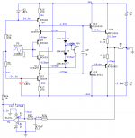
Edit: Looking at your schematic - you're missing a bias setting R or trimpot across bottom two diodes in the bias string!
You are a wise man - I noticed you stayed off this thread when it became a spec war - and now you are back - hopefully this is the turning point of the thread
Edit: Looking at your schematic - you're missing a bias setting R or trimpot across bottom two diodes in the bias string!
Krill's topology gives us an easy way to control DC offset - the disputed servo. Servo circuits are usually used inside the GNFB loop and that, reportedly, has significant impact on the sound.
But with Krill we can use servo circuit that works through upper and lower CCS, outside of the signal path.
I think that's more efficient and elegant solution than one with couple of pots/resistor networks.
But with Krill we can use servo circuit that works through upper and lower CCS, outside of the signal path.
I think that's more efficient and elegant solution than one with couple of pots/resistor networks.
Attachments
MJL, just build it or not. Quit the whining about how you feel or what someone else said. Either you are interested enough to make an effort or you are not. Simple. As I said, no excuses.
Same thing I would say to the rest of you, regardless of the effort or time you've spent on it or not.
Distortion meter? How about Dual trace scope in ADD with one channel inversed, compare input to output, adjust null pot for minimum?? Dunno.
Or use ur FFT and soundcard do a few passes based on say 4 or 5 bias settings, look for the null...
Maybe do a 19+20kHz IM for the test?
_-_-bear
anatech said:.......Hi Troy,
The pictures would be good. There may be members all over the world who may be interested in this. This may be the only way.
Having said that, you had better ask Steve first I think. He was planning to sell some boards and from what I have heard, he could use the money. Couldn't everyone though!
I am very interested in building a pair of these up, but the 100 watt version as that was the design Steve had referenced. My goal would be to use as may original part numbers as I could for this........
-Chris
I got my PCB's from Steve directly, and to my knowledge he does have more.
Whether or not he will sell them to us is another question.
He also has toroids for the 50Wpc version.
I am VERY saddened to see how he was treated on this forum. He came bearing gifts and was chastised.

jkeny said:Juma,
This is different to the one SD posted using LDRs - can you say how your servo works?
Oops, I missed that one (with LDRs) - can you please quote the post number where it's published?
The one I posted is the standard non-inverted DC servo that is found in many circuits. It's just that it controls DC operating conditions of CCS BJTs which are reflected on the output. No thrills here, just a convenient way to keep servo's output out of signal path.
- Status
- This old topic is closed. If you want to reopen this topic, contact a moderator using the "Report Post" button.
- Home
- Amplifiers
- Solid State
- Krill - The little amp that might...