Re: Okay! Enough bickering!
Why not strip out all posts that are not pertinent to "Krill - The little amp that might..."?
Moderate the personalizing. Shouldn't this thread be about the amp rather than some peoples' design prejudices and some peoples' emotional sensitivities?
anatech said:
I guess we may have to split some stuff out, and trash the noise. My first inclination would be to split the sim stuff out, but I'm open to suggestions here. To that end, what do you people want to have stay, and what should be in a different thread?

Why not strip out all posts that are not pertinent to "Krill - The little amp that might..."?
Moderate the personalizing. Shouldn't this thread be about the amp rather than some peoples' design prejudices and some peoples' emotional sensitivities?
anatech said:
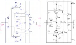
Can we post results of similar or exact circuits as long as the circuit is close to the original, and the schematic and picture is posted?
Here's mine next to the one originally posted by Steve at the start of this thread. For my purposes, this was close enough.
Attachments
Re: Okay! Enough bickering!
Three cheers for Chris!!
Thank you.
anatech said:
.........IT WORKS! Post accordingly and recognize that Steve is posting with great effort. That deserves some respect all on it's own.
-Chris
Three cheers for Chris!!
Thank you.
megajocke said:
When did R29/R30 (56.2 ohms) in the collectors of the bias transistors appear? They weren't there in the earlier schematics.
Were they used in the circuit with the claimed low distortion?
The difference in circuit operation is non-neglible.
The 1st ones I can find at 56.2 ohms are from 11 Feb Schema.
He started adding this trimmer network on 2 Feb. but the values were 220 ohms.
If you are using an older schema make sure that you have R9 (68k) going to GND and not -36 Volt regulated.
MJL & ostripper:
It depends on how much bias voltage is needed for the output stage, the devices used and so on.
If the output stage only needs a little bias voltage they will probably do harm. If the output stage needs more bias voltage for some reason those resistors are needed so that the bias transistors are kept close to (but not in total) saturation. DC offset and strange behaviour will happen otherwise.
If there is DC offset at the output it's probably an indication that they might be needed. Perhaps not the full 56 ohms, and I see there are trimmers in parallell to adjust this.
BTW, have you measured voltage drop C to E on those bias transistors in the built circuit?
OK, MJL, I thought you were being divisive in building what you did & then saying it was close enough. You can see how I felt that some major elements were left off what I considered the circuit we were all talking about, hence my accusations towards you & my request to understand what you were trying to prove!
Apologies if what you built was a genuine effort to build an accurate Krill OPS! No hard feelings, I hope
Edit: Can we all agree on a definitive schematic for the 50W, 100W & 200W output stages? The VGS isn't important, its the OPS that is unique & interesting.
Chris I don't know how you can facilitate this so that anybody visiting the thread will see these agreed schematics without having to wade through 40 pages?
By MJL - Here's mine next to the one originally posted by Steve at the start of this thread. For my purposes, this was close enough
You had to change values since you didn't use steves parts
a "nobrainer".
Same with using the 2sc/sa 's for the drivers , my krill
oscillated , so I added resistors.
I also used the KSA's for the bias gen, but had to up the
CCS currents to 10mA to get crossover distortion to
a acceptable level. VERY predictable outcomes.
None of this "bastardizes" the original design , since the
outcome is the same...it works.
OS
megajocke said:MJL & ostripper:
It depends on how much bias voltage is needed for the output stage, the devices used and so on.
Again, I wasn't looking for audio nirvana here, just to see if this configuration behaves as my sim suggests.
The sim indicated "relatively low distortion"- this is not visible on a waveform on my scope - check.
The sim said "stable" - this is definitely visible on the 20k squarewave - check.
Sums up what I wanted to know for now. I may build a more permanent version (but, like everything else I build, it will not be the "by the book design").
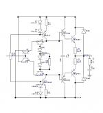
I have reviewed the latest schematic and stripped out the ancillary BS (not entirely necessary to the circuits basic operation). It's attached - compare it to mine.
Attachments
c2cthomas
When you are referring to an old schematic and some values on resistors and so on, I think it would be ok if you post the schematic you are talking about in your post. As you know it has been some schematics in this thread.
megajocke
You are right in what you are saying.
Cheers
Stinius
When you are referring to an old schematic and some values on resistors and so on, I think it would be ok if you post the schematic you are talking about in your post. As you know it has been some schematics in this thread.
megajocke
You are right in what you are saying.
Cheers
Stinius
By jkeny -Can we all agree on a definitive schematic for the 50W, 100W & 200W output stages
That is matter of device choice. I have noticed that in
the most popular DIY amps (DX and quasi amps) they
use MJE340/350 or TIPXXX almost exclusively. The reason for
this is worldwide availability.
In most of the diy amps a substitute can be used (standard EF)
with no problem, but not in the krill.
maybe multiple groups of krills (power levels / common devices)
this would allow more to build it.
OS
MJL21193 said:Again, I wasn't looking for audio nirvana here, just to see if this configuration behaves as my sim suggests.
The sim indicated "relatively low distortion"- this is not visible on a waveform on my scope - check.
The sim said "stable" - this is definitely visible on the 20k squarewave - check.
Have you done some basics like measuring the o/p bias current, o/p offset? How about slapping some caps across the o/p and showing the scope trace? Try a 100nF in series with 0.2 ohms at 100KHz squarewave, 1Vpk.
anatech said:Hi jkeny,
So, I really don't want to pick any fights here, although some of you might be upset with me right now. That is one of the perks of being a moderator. Some members will resent you because of the job.
Ha, and this is what you wrote to me in the Blowtorch thread:
anatech said:Hi Joshua_G,
Well, actually there are certain behaviors that trolls exhibit. Right now I am wondering about you.
Why?
Mostly because of the way you deal with other members and ideas. You seem to enjoy asking a question with the intent of stirring things up when you have no intention of learning or sharing. This is just my impression from reading many of your posts. The link to that other board was illuminating as well. Same behavior, similar responses from other members. I see a theme running there.
I do have a question for you though. Starting with this statement:
Okay, I'll bite. What type of recording engineer are you? What type of music do you normally work with, and what type(s) of consoles and recording devices do you use? Are you a Studer guy, or a Fostex guy?
I have met many recording engineers over the years as my work put me in a support position for them. These engineers have run the entire range of personalities. I am curious about someone who claims to be a recording engineer because there is a very wide range here.
-Chris
And:
anatech said:Hi Joshua_G,
LOL!
You really don't add much here, except for comic relief. You are acting like you've always wanted to moderate a forum, but you haven't a clue when to moderate and when tobe quiet.
I understand you want to be John's little cheering section, but he really doesn't need one. He can stand on his own two feet, all by his little self.
MJL21193 said:
I have reviewed the latest schematic and stripped out the ancillary BS (not entirely necessary to the circuits basic operation). It's attached - compare it to mine.
So, you improved Steve's design.
Good for you.
traderbam said:
Have you done some basics like measuring the o/p bias current, o/p offset? How about slapping some caps across the o/p and showing the scope trace? Try a 100nF in series with 0.2 ohms at 100KHz squarewave, 1Vpk.
Hi traderbam,
I didn't do anything other than build it, connect it and look at and photograph the scope.
Everyone who is curious about this circuit should take the time to build it, to run the tests you suggest, to take those measurements.
It wasn't difficult.
MJL21193 said:I have reviewed the latest schematic and stripped out the ancillary BS (not entirely necessary to the circuits basic operation). It's attached - compare it to mine.
Oh, so I was wrong - you don't want to build the Krill OPS just you're variant or are you just trying to defend your original circuit? You've left out Rs & trimmers which are for offset & bias adjustment!
Suggest that some folks here need to switch to "decaf" and/or try some doctor prescribed "mellowing" medicine?
I think that the sim is good to discuss. Discuss, not confront or be contentious.
If I were a moderator, I think that i would have "adjusted" some attitudes by one means or another long ago. I think this shows that there is a wide latitude and relative lack of censorship.
Imho this comes roughly under the heading of "shouting fire in a crowded theater". To make the idea clear, I'm referring to the idea that there should be no self censorship nor moderator "censorship" - meaning that everyone should just spout off the very first thing that comes into their head. Eh?
It's not the technical or informational content of some posters, it is the deliberate and explicit or implicit tone, attitude, that has nothing to do with anything factual or informational.
Let's say this about what I just said: I'm being diplomatic.
_-_-bear
"...comes a time when the blind man takes your hand and says don't ya see..." - Jerry Garcia & Robert Hunter
posted by jkney
Edit: Can we all agree on a definitive schematic for the 50W, 100W & 200W output stages? The VGS isn't important, its the OPS that is unique & interesting.
Edit: Can we all agree on a definitive schematic for the 50W, 100W & 200W output stages? The VGS isn't important, its the OPS that is unique & interesting.
Great idea. I've decided to build the output stage (OPS) and for testing purposes I will use an OPA445 as the voltage gain stage (VGS). I am working from Steve's post #805 and BOM from #809 for the 50W version.
Given the OPS tests well, I plan to use a much different VGS and use 2 amps in bridged mode.
And bear - once again you are right on the mark.
By jkeny -you don't want to build the Krill OPS just you're variant or are you just trying to defend your original circuit?
Nobody seems to "get it" here. if you use different devices
you MUST make a variant of the circuit. It is not "improved",
,but needed for proper operation with
different devices.
The same as if you swap LTP devices , your input stage
would require different degeneration resistors and/or
a different compensation scheme.. not improved , but
required for proper operation.
OS
- Status
- This old topic is closed. If you want to reopen this topic, contact a moderator using the "Report Post" button.
- Home
- Amplifiers
- Solid State
- Krill - The little amp that might...