Bogdan (Kent) Borko, polite people do not avoid answering the questions.Or you have no any argument for your claims.
All in all I am pleased to have exact clone of this legendary piece of equipment and I wish to thanks Mr. Gilmore for designing perfect PCB for this very advanced DIY project.
All in all I am pleased to have exact clone of this legendary piece of equipment and I wish to thanks Mr. Gilmore for designing perfect PCB for this very advanced DIY project.
I have finished building KSA-5 clone today. It works perfectly well-no noise, no hum , just neutral and dynamic sound. I have to put it in a enclosure now.
Dear Sir,would you please share the power supply schematic to me? thanks
Visit Head Case forum for more information.
thanks you so much.I have found the link to download the file,but I tried many time,it always downloaded failed.
I would like to know what part number for the Q1/Q4,Q2 and Q7.
you help will be great appreciate.
Best regards
xiaojun
Thank you so muchQ4 and Q7 are MJ 15024 and MJ 15025. Q1 and Q2 are out of production MPSW transistors , and I use similar parts BC639 and BC 640.
I suggest you to read Head Case forum for vital information about KSA-5.
Just completed this little side project of mine, the KSA5. Since all the info is scatter in different forums, and or posts, I decided to post all my documents in one location. It may be use to some other.
I made my own PCB, using Kevin Gilmore Gerber images, and the schematics. I made them slightly smaller so they will fit into the nice Krell clone enclosure. Kevin's own PCB don't fit.
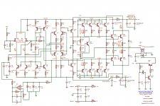
The amp schematic has multiples notes and voltage measurements for easy test.
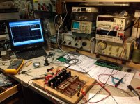
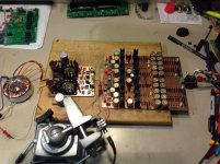
I used matched pair of 2SK170 for the input JFET, had them in stock. The rest is all quality part all around, Vishay RN60D resistors, Vishay 2 ohms power resistors, Wima & Kemet film caps, Mica frequency compensation caps, Nichicon Muse Gold caps, my own 'pure copper pcb'") , KMH filter caps on the supply.
, KMH filter caps on the supply.
I matched all the transistors with care using a curve tracer. Here my prototype.
I made my own PCB, using Kevin Gilmore Gerber images, and the schematics. I made them slightly smaller so they will fit into the nice Krell clone enclosure. Kevin's own PCB don't fit.
The amp schematic has multiples notes and voltage measurements for easy test.
I used matched pair of 2SK170 for the input JFET, had them in stock. The rest is all quality part all around, Vishay RN60D resistors, Vishay 2 ohms power resistors, Wima & Kemet film caps, Mica frequency compensation caps, Nichicon Muse Gold caps, my own 'pure copper pcb'
, KMH filter caps on the supply.I matched all the transistors with care using a curve tracer. Here my prototype.
Attachments
Last edited:
Here the measurements:
Sensitivity: 1.25Vin max, for 6.9Vac Out Max. into 8 ohms
Power: 5.95W into 8 ohms max. (+-21V supply)
BW (Ref 1Khz, 1V): 0.3Hz to 145Khz
Noise (gnd input): 0.08mV (Lab. power supply), 2.2mv (Standard Supply)
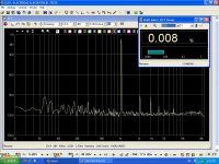
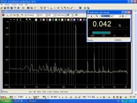
THD (1V, see load): 0.042% (8 ohms), 0.007% (16 ohms), 0.008% (no load)
IMD (1V, 1 & 2Khz): 0.007% (16 ohms)
In normal use, max volume, gnd inputs, no noise can be heard...
Excellent specs, now time for listening
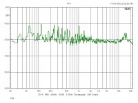
Check the FFT spectrum, From left to right
Noise floor, with lab power supply, into 8 ohms
THD, 1Khz, 1V, into 8 ohms
THD, 1Khz, 1V, into 16 ohms (more realistic load probably...) We can see than the first harmonic is higher than the next, good. Anyway distorsion is so low...
THD, 1Khz, 1V, no load
IMD, 1Khz & 2 Khz, into 16 ohms
Sensitivity: 1.25Vin max, for 6.9Vac Out Max. into 8 ohms
Power: 5.95W into 8 ohms max. (+-21V supply)
BW (Ref 1Khz, 1V): 0.3Hz to 145Khz
Noise (gnd input): 0.08mV (Lab. power supply), 2.2mv (Standard Supply)
THD (1V, see load): 0.042% (8 ohms), 0.007% (16 ohms), 0.008% (no load)
IMD (1V, 1 & 2Khz): 0.007% (16 ohms)
In normal use, max volume, gnd inputs, no noise can be heard...
Excellent specs, now time for listening
Check the FFT spectrum, From left to right
Noise floor, with lab power supply, into 8 ohms
THD, 1Khz, 1V, into 8 ohms
THD, 1Khz, 1V, into 16 ohms (more realistic load probably...) We can see than the first harmonic is higher than the next, good. Anyway distorsion is so low...
THD, 1Khz, 1V, no load
IMD, 1Khz & 2 Khz, into 16 ohms
Attachments


Last edited:
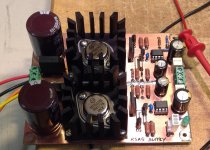
After a few listening tests I settle for a slightly lower supply voltage, and higher bias, 19V, and 125mv bias (instead of 21V, 100mv). I found that the sibilance are lower, and the overall sound smoother.
For those who wonder the Heatsink temperature is around 45C, with 19V supplies and 125mV bias, with the prototype in open air.
Will be at least around 50C once monted inside the enclosure. I'll have ventilation added on the bottom, my PCB has ventilation holes under the heatsinks.
It should form a nice ventilation chimney from bottom to top once mounted in the enclosure.
Compare to some of my best Headphone amps, this one is very detailled, doesn't hide or improve anything, bass are well controlled.
To resume a very nice amplifier, but more on the side of the revealing than on the side of dreamy.
It is always a question of taste
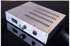
Here the chassis I will use, with integrated power supply... More on that once I'm done doing the assembly.
For those who wonder the Heatsink temperature is around 45C, with 19V supplies and 125mV bias, with the prototype in open air.
Will be at least around 50C once monted inside the enclosure. I'll have ventilation added on the bottom, my PCB has ventilation holes under the heatsinks.
It should form a nice ventilation chimney from bottom to top once mounted in the enclosure.
Compare to some of my best Headphone amps, this one is very detailled, doesn't hide or improve anything, bass are well controlled.
To resume a very nice amplifier, but more on the side of the revealing than on the side of dreamy.
It is always a question of taste
Here the chassis I will use, with integrated power supply... More on that once I'm done doing the assembly.
Attachments
Last edited:
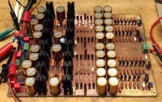
I matched all the transistors pairs that I could see on the schematic, indeed you cannot match PNP with NPN. Matches are only within NPN or PNP.
In addtion to the pair of output power transistors, I also matched the following
-Q5, Q6 (Input JFET CCS pair)
-Quad Q15-Q18 & Q19-21 (Output transistors drivers)
And these that may or may not be in need for a match, I didn't know:
-Q11 with Q9 & Q8 with Q7
-Q10 with Q4 & Q3 with Q2
The small signal MPS06 & MSP56 were easy to match. I bought 100 of each, but only needed to measure the first 50 to find suitable match.
The power transistors had more variability, and were more difficult to find match. I bought 30 of each, and that was just enough... I still have a few extra matched pairs but they are less closely matched than the ones I'm using.
In the actual amp, if I measure the accross the 2 ohms resistors, for a bias of 125mv, all 4 resistors measured within +/-1 mv of each, indicating closely matched output pairs.
Once the amp was completed, without plugin the servo IC, I had -0.06V and -0.08Vdc at the output, also indicating a well balanced circuit. The Servo was almost not needed...
Last edited:
Here the latest tweaks, as I said lowered the supply voltage to +-19V, easily done, simply added 2K on parallel with the reference output volt divider 511R.
Then on the supply added an input CRC filter (4R resistor and second 4700uF cap) to reduced a little the regulator input voltage from 32V to 30V, since I increased the bias current.
That will reduces the pass regulator power dissipation.
That also reduce the amp already low noise floor. Regulator input ripple went from 300mVac to 100mVac...
End result is very nice indeed, excellent amplifier
Attachments
Why 10ma Idss for input J-Fets ? Is it important? I useK170 with 8ma Idss.It seems that original 2N fets are better since they have much lower input C.
Kevin Gilmore designed improved PS version for KSA5 called Golden Reference LV. I built it, and and SQ was improved in dynamics and bass.
Kevin Gilmore designed improved PS version for KSA5 called Golden Reference LV. I built it, and and SQ was improved in dynamics and bass.
Contact me on PM for GR gerber file.It is in fact high current Jung SR.8ma is probably better match, I had recycled pairs matched at 10ma, so i used them... Do you have the info for this improved supply?
Attachments
- Home
- Amplifiers
- Headphone Systems
- Krell KSA5