jacco vermeulen said:Aussies vacuum, thats not for the Mrs ?
What is the world coming to !
Oooo la la!
Don't let her hear that!!!
No, i don't mind vacuuming! It's not fun, but it has to be done!
wim said:Is the loudspeaker protection kit from Velleman (K4700) a good one, and can it be used for the Krell-clone? It is a cheep stereo PCB.Or is it better to use a relais per channel from Amplimo (LRZ loudspeaker protection relais)? Cheep also.
Or is it better to use a protection circuit as used in a bunch of diy projects by Elrad, Elektor, etc. Cheap also !
With DC-sensing, softstarting, speaker-impedance measurement, peak current protection, toroid secondary voltage check.
Can be built on a 2.5" x 5" piece of experimentation
board, or i can email the layout to you.
Hell, Wim, i'll even drop a few relays in your Ypenburg frontdoor slit !
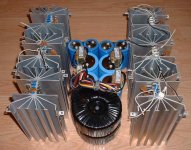
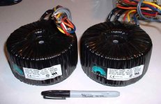
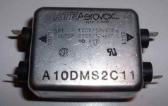
Here my big parts for the amp. Two big 750VA Plitron transfo, 8 caps and 1.5mH, 5A chokes for a CLC filters, 6 big heatsinks (2 fets per heatsink) and two 10A EMI filters.
I'm planning a dual sections central casing (like Lamm amps).
I 'll put the soft start PCB, EMI filters, dual rectifiers per channel, the first Caps section and the chokes under a bottom section.
Then the two big transfo, the final caps and the PCB on the top.
I'll try also the build an balanced receivers pcb to have balanced and single ended inputs.
The total width will be 16.5 inches. So the complete amp will be 19" rack size.
Attachments
Do you take kindly to people borrowing your components and keeping them? ") Good stuff there!!
Good stuff there!!
I saw this auction on eBay for the KSA-100, he has some PSU numbers that can be derated for KSA-50. 1.1kVA trafo plus 80,000uF... so 550va and 40,000uF for KSA-50. Tsk Tsk does Dan D reckon we will go for such puny PSU's? HA!
http://cgi.ebay.com/ws/eBayISAPI.dll?ViewItem&item=5757618551&ssPageName=ADME:B:SS:US:1
Good stuff there!!I saw this auction on eBay for the KSA-100, he has some PSU numbers that can be derated for KSA-50. 1.1kVA trafo plus 80,000uF... so 550va and 40,000uF for KSA-50. Tsk Tsk does Dan D reckon we will go for such puny PSU's? HA!
http://cgi.ebay.com/ws/eBayISAPI.dll?ViewItem&item=5757618551&ssPageName=ADME:B:SS:US:1
Nice pitures of the KSA 50
Se this for nice pictures of the KSA 50
http://home.wanadoo.nl/laetitiakonijn/audioset.htm#cd
Peter
Se this for nice pictures of the KSA 50
http://home.wanadoo.nl/laetitiakonijn/audioset.htm#cd
Peter
Can anyone tell me the values of c5 and c6 on the original kas50 board. The ones I have removed from my amp are marked roe 1000/16 s8 ek, acording to Lloyd Macleans drawings they should be 100uf. My amp is a 240v type but I am assuming all the boards are the same. also the bias on my amp is about 440mv but acording to the same drawings it should be 620mv.Lloyd if you read this post maybe you could comment.
Finaly can anyone tell me a supplyer for 40000uf 75vdc caps.
Many thanks Iain
Finaly can anyone tell me a supplyer for 40000uf 75vdc caps.
Many thanks Iain
beckypumps said:Can anyone tell me the values of c5 and c6 on the original kas50 board. The ones I have removed from my amp are marked roe 1000/16 s8 ek, acording to Lloyd Macleans drawings they should be 100uf. My amp is a 240v type but I am assuming all the boards are the same. also the bias on my amp is about 440mv but acording to the same drawings it should be 620mv.Lloyd if you read this post maybe you could comment.
Finaly can anyone tell me a supplyer for 40000uf 75vdc caps.
Many thanks Iain
Do you want some 50v 68000uF
.By the way for 2 pairs of T0-3's with 1 ohm emitter resistance, you need 900mV across them for 50w class-A.
beckypumps said:Can anyone tell me the values of c5 and c6 on the original kas50 board. The ones I have removed from my amp are marked roe 1000/16 s8 ek, acording to Lloyd Macleans drawings they should be 100uf. My amp is a 240v type but I am assuming all the boards are the same. also the bias on my amp is about 440mv but acording to the same drawings it should be 620mv.Lloyd if you read this post maybe you could comment.
Finaly can anyone tell me a supplyer for 40000uf 75vdc caps.
Many thanks Iain
They are 16v 1000uf caps...
Can you look at the board and tell us the writing on the C6/C7 - they are near the "drivers" on the main board and are usually a dark purplely/red colour.... This is a value we have been desperately seeking as to what it actually is!! Can you help with that?
THanks
Aaron
"Can you look at the board and tell us the writing on the C6/C7 - they are near the "drivers" on the main board and are usually a dark purplely/red colour.... This is a value we have been desperately seeking as to what it actually is!! Can you help with that?"
I don't think we are all that desperate! The values specified on Jan's drawing works just fine. At least one person in this thread has used 39 pf caps in place of the 390's. I used 330pf in mine, it sounds just like a Krell! The original Krell KSA-50's and even the KSA-100 Mk-2 did not have the 100 pf caps, C107 and C108 as per the drawings on Lloyd Mclean's site here......http://home.ca.inter.net/~lloyd.maclean/Krell/Krell.htm
You could probably leave them out without any problem.
Mark
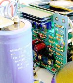
After I Photoshoped a cropped section of the photo this board looks quite different from what we are building.... I wonder what the transistors are on the lower heat sink.... perhaps yet another version.......? So the Dan man only used 40,000 mfd in the originals.......
Mark
Mark
Attachments


New thread for pictures
Hi All-
I'm hijacking Mikes thread to use for pictures .
He has started one and I will routinely put it in this thread for reference.
http://www.diyaudio.com/forums/showthread.php?s=&postid=593399
Hi All-
I'm hijacking Mikes thread to use for pictures
.He has started one and I will routinely put it in this thread for reference.
http://www.diyaudio.com/forums/showthread.php?s=&postid=593399
OK, time to get this thread going again.
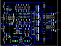
Well, my original plan was to etch my own pcbs with Jan's design, but as I am still waiting for some parts, and some parts I have are slightly different to the reference design, I thought I would have a go at rolling my own...
Below is the result. It was a little difficult fitting everything in with the free version of Eagle, but I like a challenge! This is still a work in progress however, so don't just copy it and use it. I have swapped the trimmers for Bourns, and R127 and R128 have facility for mounting several lower wattage versions in parallel. I tried to get all the power transistors in a nice line for heatsinking, as on the original, and I also lost the 100p caps on Q109 and Q110. If needed, I will just solder them on underneath. R124 is also mounted on the bottom. Oh, and the I/V protection has gone.
I am thinking of using a double sided board, with the whole of the top layer, (apart from the feedback trace) being a groundplane. Any opinions?
Attachments

- Home
- Amplifiers
- Solid State
- Krell KSA 50 PCB