Hi all,
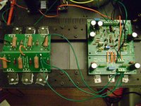
Jozua, By pass caps were 4.7uf and 0.1uf polypropolyne, I thought they would be OK, any suggestions. Thanks for your kind words about the build but this was an earlier version that I have now scrapped. I included those pictures for henryve as he is building a passively cooled clone and I thought they may have been some use for him.
Jushuota, sorry no circuit diagram, resistors were for the CRC and caps were as mentioned above.
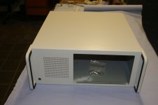
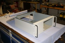
I have not yet started to assemble the final version (I hope) of my clone into its chassis, although it has been running on the bench for a couple of weeks ( one channel only) If anyone has suggestions please let me know, I have much to learn.
Alan
Jozua, By pass caps were 4.7uf and 0.1uf polypropolyne, I thought they would be OK, any suggestions. Thanks for your kind words about the build but this was an earlier version that I have now scrapped. I included those pictures for henryve as he is building a passively cooled clone and I thought they may have been some use for him.
Jushuota, sorry no circuit diagram, resistors were for the CRC and caps were as mentioned above.
I have not yet started to assemble the final version (I hope) of my clone into its chassis, although it has been running on the bench for a couple of weeks ( one channel only) If anyone has suggestions please let me know, I have much to learn.
Alan
Alan
Your only problem was that your heatsinks were too small. From some simple calculations that I did with various heatsink models that were available it became quite clear that around 450mm X 180mm X 75mm was the minimum required for one channel of the KSA50 clone. I only made mine 200mm because the supplier cut the heatsinks to standard sizes, and 200mm was one of them.
I suspect that I will be able to run my clone at around 55W in winter. Summer; no chance in hell as we regularly hit 35 - 42 degrees Celcius ambient, but I have a plan.
I will build myself a unit with some fans like Choky's Amp babysitter on which the amp will be placed. It would then move air over my heatsinks from bottom to top. Simple really.
BTW Alan
I don't think you will have a problem with those bypass polypropylenes. In fact, I populated the rail bypass caps spots on my PinkMouse boards. A 470uF 50V Panasonic FM together with a WIMA MKP 100nF should do it. I think those you have should also be OK. They should filter the high frequency noise from the rails and clean up your high frequency information in the signal.
I don't think you will have a problem with those bypass polypropylenes. In fact, I populated the rail bypass caps spots on my PinkMouse boards. A 470uF 50V Panasonic FM together with a WIMA MKP 100nF should do it. I think those you have should also be OK. They should filter the high frequency noise from the rails and clean up your high frequency information in the signal.
Hi,
henryve,the heatsinks I used on the build I posted pictures of may have been marginal but please bear in mind that I was using 25V rails and 1.7A bias, dissapating 85W per channel so heatsink required was 0.35C/W. I was not so much worried about the temperature that the sinks reached, I was much more concerned with the fact that all the internal components also reached that temperature. If I was going to use passive heatsinks again I would try to thermally isolate them from the rest of the chassis.
I saw (I think) from your pictures that your construction appears to be the same as I used. I am not technically qualified enough to offer advice, but I would certainly bear it in mind. How much heat are you intending to dissapate per channel?
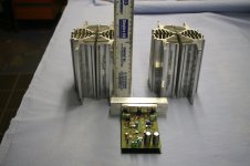
I have decided to use two heatsink towers as per KSA100 and run fans at approx 5V making them virtally inaudable. If I were to use passive heatsinks for this build I would need to have approx 0.187C/W sinks per channel.
Rails are 42V bias 1.9A = 160W heatsink towers approx 140mm tall.
Alan
henryve,the heatsinks I used on the build I posted pictures of may have been marginal but please bear in mind that I was using 25V rails and 1.7A bias, dissapating 85W per channel so heatsink required was 0.35C/W. I was not so much worried about the temperature that the sinks reached, I was much more concerned with the fact that all the internal components also reached that temperature. If I was going to use passive heatsinks again I would try to thermally isolate them from the rest of the chassis.
I saw (I think) from your pictures that your construction appears to be the same as I used. I am not technically qualified enough to offer advice, but I would certainly bear it in mind. How much heat are you intending to dissapate per channel?
I have decided to use two heatsink towers as per KSA100 and run fans at approx 5V making them virtally inaudable. If I were to use passive heatsinks for this build I would need to have approx 0.187C/W sinks per channel.
Rails are 42V bias 1.9A = 160W heatsink towers approx 140mm tall.
Alan
Alan
I calculated around 160W per channel if I bias at around 1.9A. My rails should be around 41V each. This means that my heatsink should have a Rth of at least 0.1875 at Ta = 25 deg C. I think mine is around 0.11. I get what you said about only having 25V. I just don't think you should have given up on your first version that easily. You could have just used an extracter fan if the heat inside was too much. That power module for your first version is done so well, I would cry if I had to scrap it. Hope you kept it around since that power module and heatsink would be ideal for an F5, just change the transformer.
I intend on having lots of holes on the bottom and top covers. Basically about 60% of the area on the top plate will be perforated, and about 30% of the bottom. The proof however is when I start biasing.
Last edited:
Alan
If you ever want to part with those heatsink tunnels, please let me know......
However I have some reservations if your enclosure is strong enough for the heavy innards.
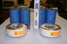
Consider yourself very lucky to have those Spraque caps as their price has nearly doubled - even worse when you have to import them at a exchange rate of R8 = $1 plus shipping and duties....
Regards
Jozua
If you ever want to part with those heatsink tunnels, please let me know......
However I have some reservations if your enclosure is strong enough for the heavy innards.
Consider yourself very lucky to have those Spraque caps as their price has nearly doubled - even worse when you have to import them at a exchange rate of R8 = $1 plus shipping and duties....
Regards
Jozua
Jozua
If you sell one of your Krell amps you will be able to get those heatsink tunnels from Fischer Electronic, locally distributed by Electrocomp (Electrocomp -- Complete solutions. Do it better.).
You will want the LA1 type extrusion.
If you sell one of your Krell amps you will be able to get those heatsink tunnels from Fischer Electronic, locally distributed by Electrocomp (Electrocomp -- Complete solutions. Do it better.).
You will want the LA1 type extrusion.
Henry
Not what I have in mind but I will note the suggestion.
Regards
JH
Jozua
Are you refering to the Fischer extrusion or the selling of a Krell?


STep one...make sure your grounds are set up correctly. Both the input and the outputs to the boards. Mine was tripped up and it took me three days to figure out the problem...
Also had a 220k resistor instead of a 220R resistor on the output board...which didn't help...
Also had a 220k resistor instead of a 220R resistor on the output board...which didn't help...
If I remember correctly, the input hot and ground go to the board. The power ground also connects to board.
Check your resistor values too on output board....
EDIT - for biasing, I think you are correct, but make sure your grounds are properly connected anyway, and see if it makes a difference...
Check your resistor values too on output board....
EDIT - for biasing, I think you are correct, but make sure your grounds are properly connected anyway, and see if it makes a difference...
That output board resister is 2r2, right? Not 220R.
I built mine using bom from this post, is everything correct?
http://www.diyaudio.com/forums/solid-state/31077-krell-ksa-50-pcb-424.html#post728457
I built mine using bom from this post, is everything correct?
http://www.diyaudio.com/forums/solid-state/31077-krell-ksa-50-pcb-424.html#post728457
- Home
- Amplifiers
- Solid State
- Krell KSA 50 PCB