Hi
Jan what do you think about Finder relays? I find the type 5000 12 V DC with gold plated contacts, 10 A constant current 380 V AC, 20 A peak. They are silent. With two in parallel we have 40 A in peaks. I think it's O.K. Dimensions are 29mm x 12.4mm. What everybody else thinks?")
Jan what do you think about Finder relays? I find the type 5000 12 V DC with gold plated contacts, 10 A constant current 380 V AC, 20 A peak. They are silent. With two in parallel we have 40 A in peaks. I think it's O.K. Dimensions are 29mm x 12.4mm. What everybody else thinks?
K-amps said:Aaron your calcs are good... but you are only getting 1.6 watts of class-A output (at an efficiency of 5.88%) rest of your output upto 100 watts is class-AB/B. What OP devices are u using?.
Good for testing though.
Onlly 1.6w? Damn! i'm using MJ21193/94... However i wasn't cranking it at all, and it's definately loud enough (without leaving class A) to make noise
Low efficency!! i guess i'm only running 1 set of outputs wim said:NUTTTR, i asume you lower the value of C105 and C106 from 330 PF to a lower value, like 33PF or 47PF? Can you tell us what brand and type the new C's have, i can not find good quality C's with that value.
I used 47pf BC Components polypropolene
Aaron
MikeW said:The 330's work. If you replace them with something to low there will be high frequency oscillation. I tried it with 22's and 33's. NFG.
Mark previously said that there was some (10khz+) attenuation with the 330pf caps.... I've used 47pf and noticed no ill effects... i haven't got a scope to test it, and it's thermally very stable.... is there any way i can test for HF oscillation without a scope?
Aaron
ACD said:Parts list update:
Please let me know the suggested values for:
R124
C105 and C106
ZD101 and ZD102
for R124 i used 4.7k ohm, it seems to work so far!
C105/106 i used 47pf
ZD101/102 i used a 27v 3w zener (i was what i could get at the right price!) it sits about 50deg with 43v rails...
Aaron
r124...
...is definitely 4.7k, or something close to it. Anything wildly outside this range will change the range over which the Vbe mult, and therefore the bias can be adjusted over. Too much will be catastrophic, too little would be pointless.
The zener diodes ZD101 &102 are 27v in the ksa50 and IIRC the ksa100. If someone wants to use much lower rails they will need to be reduced in value, but then so will a bunch of the resistors that feed them. I can calculate some values for people if they want them, but they would be theoretical and some experimentation would be needed to make sure the result was worth the effort.
Stuart
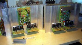
Here's where I'm at so far. The module on the right has been run for anout 10 hours... 36 volt rails at 1.8 amps bias level/400 mv resistor drop as in K-Alps calcs. This was with a smallish fan runing slowly and the sink temp was a mild 48 deg c. which is very reaonsble. That channel sounds very good. Offset can be adjusted to 0 mv and seems to hover there or right around just a few mv max over time. I think that I will turn both these sinks face to face and make a wind tunnel out of them for best efficiency. 2- 3" fans running slowly to keep the sink temp reasonable. The main sink seems to pretty much track what the driver stage is doing as far as temperature. I still have my 330 pf caps in there but plan on lowering them when time permits for testing.
Has everyone used C107 & C108 in theirs or not? The original KSA-50 did not have them and I plan on yanking them out of mine, but one thing at a time....... This may also be attributing to the rolloff I see on a 10 khz square wave...... looks more like a triangle wave. I also omitted the base resistors on mine so as to stay as close to the original as possible.......
Mark
Attachments
Could anyone please correct me if I'm wrong?
I looked at the schematic downloaded from the website of delta-audio. The input diff pair is biased at about 1.48ma/transistor (27V/9.1k/2), so the voltage across the collector resistor should be around 2.2V, which makes the current through R120 0.46ma.
Don't you think it's a bit too small, the second stage biased at a current even smaller than the input stage and driving a mid-power transistor?
Sounds like something is wrong to me.
current...
EJ,
I worked back from the outputs, and my (potentially wrong) calculations suggest there is about 3ma per transistor in the Diff pairs. All my errors are pretty well compounded by the time we reach the front end and I haven't tested one, so I can't claim anything more than theory, but perhaps one of our builders can measure the voltage across R117 or R116 for us...
The MPSA transistors with the MJE's that follow are effectively elaborate darlingtons, with the huge current gain implied. If the pair have a gain of 250 x 50, the diff pair running at even 0.1ma wouldn't be a problem.
I think the Vbe multiplier 'group' has ~25ma, ie R122/R123 carry 25ma, ~1ma of which goes through the resistor chain and ~24ma through Q11, if this is the case, just a few uA is pulled from the diff pairs...
Aaron, Mark, would you mind measuring the voltage across R107, R117, R120 and R123 for us, it would be good to have a deeper understanding of the inner workings. Plus k-amps will like the results of my calculations better if there is some confirmation that I am on the right track.
Stuart
Krell KSA50 Box
Hi
I am just wondering if there is interest in a possible group buy for for two box types. I am thinking of having two versions made namely a internal fan cooled box (similar to the original KSA 50 minus the massive handles ) and a stereobox onto which external heatsinks can be mounted similar to the KSA80 B.
The speaker connectors , mains input and signal input can be predrilled. The only uncertainty I have is where to put the on-off switch and what type of custom switch should be used- especially if a expensive facia is made.
Interested parties can contact me at: hugot@icon.co.za
Jozua
Rails: 42.7v
Across appropriate resistors (voltage drop)
R107 - 42.1v
R117 - 2.14v
R120 - 1.59v
R123 - 1.02v
How's that?
Aaron
P.S. Are my rails too high?! I know they are unloaded (essentially), but will my 800va toroids when loaded with about 3.3amp worth of bias (one toroid per channel), will they be up around 40+v??
With that size of traffo regulation should be quite good, so I doubt you will see more than a volt or so drop when loaded. If it's any consolation, I will have similar rails for my version.
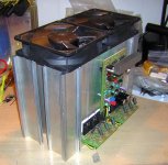
Here's the heatsink I just bought from Ebay, I just hope that with a fan or two and a bit more ducting it will work ok.
Here's the heatsink I just bought from Ebay, I just hope that with a fan or two and a bit more ducting it will work ok.
Hmmm
Thing is i have 28vac rails now (!), maybe it's a 220v toroid? I get 250v mains here...
Maybe that's it? No idea why it's so high to be honest...
28vac can't be 42vdc, surely?
Aaron
[edit - found out why!! i'm getting 32.8v rails off the toroid, it's a 230v toroid! I have 250v mains at the moment... It varies between 245v-250vac pretty consistantly.... We haven't had lower voltage than that that i've ever seen....]
Inrush?
What's the best method for limiting it? (for other members too)...
People have said for toroids over about 600va you need it, but i have a 1.2kva one here on an amp - low (20,000mfd) capacitance after it, but it's turn on thump is definately acceptable (thump = sudden current draw)... So should anyone else be worried?
Aaron
Aaron,
With a fully biased set-up, your rails will drop by at least 4 vdc but as much as 6vdc. I think you are good.
Yes Stuart, K-amps like you to have a good reference point for his calcs.
Mark, those sinks look very nice, I have one of those fans you show, diacast blades, very torquey. (Torqueful.... Torquer-fied... schucks I give up.)
- Home
- Amplifiers
- Solid State
- Krell KSA 50 PCB