16 ohms?
I'm a big fan of this amp.
I recently acquired a pair of 16 ohm drivers I want to spend some time messing with.
There are a couple of spreadsheet calculators floating around for the Klone. I know that some errors have been found in the past with them, but I'm not sure if they have related to the output power rows. According to the calculator, the KSA50 can put out considerably more power into 16 ohms than 8 ohms. What's wrong with this picture?
TIA
Attachments
you will need to go into the cells and change the formulae
I'm not a math wiz...
The speaker impedance as entered into the spreadsheet is one of the variables, same as rail voltage or Iq.
Are you saying the formula needs to be re-written for each speaker impedance?
A Krell clone
An externally hosted image should be here but it was not working when we last tested it.
An externally hosted image should be here but it was not working when we last tested it.
An externally hosted image should be here but it was not working when we last tested it.
An externally hosted image should be here but it was not working when we last tested it.
An externally hosted image should be here but it was not working when we last tested it.
Nice one.
You can post the details,circuit version used, bias, choice of output transistors, temperature on the h. sinks, some detal of the power supply, etc. What are those big film capacitorson the small boards?
The PCB is mostly the same as shown in this forum, the transformer is a R-core 1200w with 38ac. Subjectively, I found out R-core sound better for me.
An externally hosted image should be here but it was not working when we last tested it.
An externally hosted image should be here but it was not working when we last tested it.
I bought the PCB from China and the BOM are bought from RS, as shown from the list below (Sorry it was Chinese), are mostly a copy of the BOM shown in this forum, so no surprise.
An externally hosted image should be here but it was not working when we last tested it.
The temperature of heatsink could reach almost 80c when set to 500mA, I decided to tune down alot and the limits are +35c from the room temperature, ranging from 55c-65c, it would be better not to setup a heater in Hong Kong!
An externally hosted image should be here but it was not working when we last tested it.
I have also installed an auto shut down switch onto the heatsink when the temperature is over 75c.
An externally hosted image should be here but it was not working when we last tested it.
For the white cap you are asking, it was cornell dubilier 940c, which I have some extra leftover during my DIY speaker, they are good as a snubber
An externally hosted image should be here but it was not working when we last tested it.
It was a great amp, better resolution and more enjoyable than my 1st built with Sanken 2sc3264/2sa1295.
The bad thing is: it is too heavy.
The bad thing is: it is too heavy.
An externally hosted image should be here but it was not working when we last tested it.
I'd like the boards just to make some measurements on the bench. If I build a clone
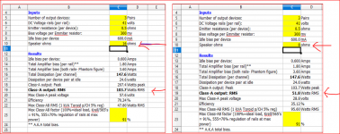
I know Pete likes technical details (as do I), so I thought I would post some numbers that I extrapolated from the KSA50 circuit values. Someone else may have already done this in the > 8k posts, but here it is:
Closed Loop Bandwidth (Unity Gain Frequency): 1.1MHz
This is based on the LTP degenerated re' resistance (100 Ohm in each emitter leg), closed loop gain of the amp (15.5) and using 39pF frequency compensation caps which seem to be a good choice.
Slew Rate: 74 V/us
This is based on the current through each diff amp (1.45mA) and the compensation caps (39pF). For a single-ended input design, the slew rate would be 37 V/us. This is all based on the math, so actual slew rate may be less in reality.
I have some KSA50 clone boards from eBay and the -3dB frequency response on the top-end is past 200kHz. I reconfigured the input high-pass filter for -3dB at 200kHz.
I found the below information from previous posts...
Krell KSA 50 pcb
I find it hard to believe that the KSA50 was only tested to have a slew rate of only 14 v/us. Design math and real world testing will yield different results, but not that much.
If you take the information from a Self or Cordell book, you can "back calculate" the slew rate of the KSA50. Even if you derate the math results (parasitic circuit capacitance's) some, the KSA50 should easily have a slew rate of 40-50 v/us (based on original power figures), which is a lot for a low power amp. Heck, the original Leach amp had 60 V/us slew rate.
I'll have to put my clone back on the test equipment and see if I can get an accurate measurement of the slew rate.
I have a set of Jan boards and pink mouse boards I am finally letting go.
After many years I have come to the realization that I won't have the time or resources to build these. It breaks my heart. I have wanted a ksa-50 since the day I first read about them.
But being a traveler I don't have a shop to build and test them and these are certainly the WRONG amps to move with frequently.
Free to a good home but I ask shipping to make sure the receiver is serious about building them and not just collecting pcbs. $10/US addresses. Overseas shipping would require research.
I have heatsinks for them too but those are not free and will have a bit more of a shipping cost.
Thanks again for a decade of hope, I have loved this thread.
Troy
EDIT: That was fast.. Already have a request. I will confirm they are taken tomorrow.
Last edited:
Won't let me edit the previous post again due to time or since I edited it once already.
I only have the pink mouse boards.
Thinking back I gave away the Jan boards when I moved and had to lighten the load. Transformers and heatsinks are heavy.
Troy
PMd
I have always wondered about "errors" on the KSA50 schematics that have been hand drawn from original circuits. I have never seen a factory schematic.
Anyway, I have modified some part values based on information in the Self and Cordell amp (and Randy Slone - RIP) books. The attached schematic is based on the Pinkmouse board, so I used the same part reference designators. The power supply bypass parts are not included for clarity.
In particular the emitter follower emitter resistor never looked right to me. With approximately 1.4VDC across R120 and R121 (3.3k) only a vary small current is flowing through the emitter follower circuit to drive the VAS.
Granted, all the klone amps appear to work OK with these circuit values, I think the original resistor for R120 and R121 was 330 Ohm.
Just like the error with the original compensation caps being 10 times too large (390pF vs 39pF), I believe these resistors are also 10 times too large (3.3k Ohm vs 330 Ohm). With a 3.3k resistor, the current in the emitter follower is approximately 420uA. With a 330 resistor, the current in the emitter follower is approximately 4.2mA. This figure makes much more sense to drive the VAS.
Increased power dissipation in the emitter follower should not be an issue, no matter what transistor you used. If it is a TO-92 (MPSA42 / 92) they might get a little warm vs them being "cool" with the 3.3k resistor.
The compensation cap connection has also been revised to include the emitter follower in the VAS local feedback loop they way it should be (according to most books I have read). Refer to C105 and C106 for the new connection method. This connection method properly loads the LTP with the calculated Miller capacitance and allows the emitter follower to drive the VAS base directly. Local VAS feedback is taken around both transistors so both transistors are compensated.
Both connection methods seem to work, but I believe including both transistor in the feedback loop yields more consistent, reliable results and may help damp tendencies for the circuit to oscillate.
The transistors in the attached schematic are the actual ones I am using in my klones.
If you are adhering to the original KSA50 circuit and are only using 4 output devices per channel, you can probably use alternate drivers; I have also used Toshiba 2SA1306B and 2SC3298B (These are identical replacements for the original Sanken 2SA968 / 2SC2238 that Krell used) for the drivers and they appear to be happy. I just happen to have a large stash of these drivers so I thought I would test them in the circuit.
I could not tell any difference in sound, but perhaps if you drive low impedance loads (or are using more than 4 output devices per channel) at higher volumes, there may be some advantage to using the MJE15032 / 33 drivers.
Main speakers I use are normally 8 Ohm.
Attachments
Last edited:
KSA50 clone
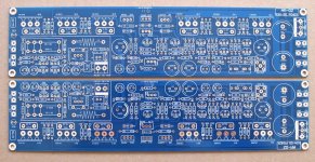
Thanks THD+N for sharing insights on the KSA50! I bought a couple of PCS from Taobao, China and they seem to be quite close to what you describe. I.e. the 390p capacitor and the 3K3 resistor.
There was no schematic so I reverse engineered it. I have seen at least a couple of other clones that look similar, for example the one from Delta in Denmark.
I will certainly try the mentioned modifications. What do you think about the values of the feedback resistors at 27K/680R? 22K/1K5 seem to be common values.
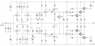
KSA50 PCB and schematic (drawing was just finished, so may contain errors):
Thanks THD+N for sharing insights on the KSA50! I bought a couple of PCS from Taobao, China and they seem to be quite close to what you describe. I.e. the 390p capacitor and the 3K3 resistor.
There was no schematic so I reverse engineered it. I have seen at least a couple of other clones that look similar, for example the one from Delta in Denmark.
I will certainly try the mentioned modifications. What do you think about the values of the feedback resistors at 27K/680R? 22K/1K5 seem to be common values.
KSA50 PCB and schematic (drawing was just finished, so may contain errors):
Attachments
Thanks THD+N for sharing insights on the KSA50! I bought a couple of PCS from Taobao, China and they seem to be quite close to what you describe. I.e. the 390p capacitor and the 3K3 resistor.
There was no schematic so I reverse engineered it. I have seen at least a couple of other clones that look similar, for example the one from Delta in Denmark.
I will certainly try the mentioned modifications. What do you think about the values of the feedback resistors at 27K/680R? 22K/1K5 seem to be common values.
KSA50 PCB and schematic (drawing was just finished, so may contain errors):
The transistors in the schematic just reflect what is printed on the PCB. I have not yet decided which transistors I will use.
- Home
- Amplifiers
- Solid State
- Krell KSA 50 PCB