found it...
...as Troy correctly surmised, it was behind my most recent sculpture, a picture of which I have attached.
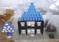
I call it "3.4 farads sitting on top of 16 heatsinks, weighed down with 500va toroids..."
very original I think, though destined for a short life...
The little black square on the front edge of the carpet fragment is an mjl21194, just for scale...
The plastic bags to the right of the sculpture are full of icky little 4700u/50v caps, for when one of the 68000/50v is just too much...
The blue boxes to the left are panasonic 0.68ohm, 10w resistors.
Some people collect stamps, what can I say, I've been called insane, but at least my friends get nice hand me downs...
Ace, we'll save the speakers for another day...
Stuart
...as Troy correctly surmised, it was behind my most recent sculpture, a picture of which I have attached.
I call it "3.4 farads sitting on top of 16 heatsinks, weighed down with 500va toroids..."
very original I think, though destined for a short life...
The little black square on the front edge of the carpet fragment is an mjl21194, just for scale...
The plastic bags to the right of the sculpture are full of icky little 4700u/50v caps, for when one of the 68000/50v is just too much...
The blue boxes to the left are panasonic 0.68ohm, 10w resistors.
Some people collect stamps, what can I say, I've been called insane, but at least my friends get nice hand me downs...
Ace, we'll save the speakers for another day...
Stuart
Attachments
mjl21194 outputs
Jan,
When I was talking about doubling or tripling I meant from 2 to 4 to 6 pairs, so the trio of mjl parts will be easy. Based in the datasheets the transistor is generally better, with more linearity to begin with, so I think if there is a difference at all, it will be in favor of the 21193/4s.
I am going to try both the original pair and the newer triple, the latter with more Re to keep the overall bias equal...
Stuart
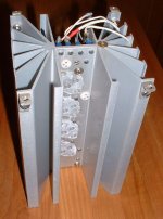
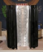
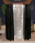
This is the radiator I'll use. I got 6 of these 5"X4.5", lenght 8''
From the Wakefield catalog I think that is 0.8 deg C/W.
I'll put two transistors per heatsink, 3 heatsinks per side.
From my quick calculation, with supply of about 38V (Transfo of 28Vac), PWR = (37V - 0.55V) * 1.1A biais = 34W.
So for 30C above ambiant of 20C (heatsink temp of 50C), the heatsink is 30C/34W = 0.88C/W, so a 0.8C/W should be Ok.
Attachments
I call it "3.4 farads sitting on top of 16 heatsinks, weighed down with 500va toroids..."
My Aelph X has 2 Farads comprised of 8 x 250,000 uF Caps.
"This is the radiator I'll use. I got 6 of these 5"X4.5", lenght 8''
From the Wakefield catalog I think that is 0.8 deg C/W.
I'll put two transistors per heatsink, 3 heatsinks per side."
______________________
Thats a very similar sink to what I used on my overly biased Aleph 2's. On mine I used 6 per monoblock that are 6" tall. Very similar to what Krell did. They are among the most efficient sinks made. Wakefield is a pain in the you know what to deal with but they are also available from M&M Metals and they are very nice to deal with. Total cost on mine(unanodized) was just over 300 bucks U.S. with the shipping. Here is the link......
http://www.mmmetals.com/pages/mediu..._heat_sinks/high_power_extruded_heat_sink.htm
Mark
About radiators...
Hi All-
I spoke with Steve @ Apex.jr last night about another project I have going on and he said he just bought some heat sinks.
I am trying to get a picture of them so I can see if they would work for us too.
He has these on his site too, but I will wait to see the others.
http://www.apexjr.com/images/APEXJRTUNNELHEATSINK2.jpg
http://www.apexjr.com/images/APEXJRTUNNELHEATSINK1.jpg
I also bought fifteen 50 VDC caps from him for this project.
http://www.apexjr.com/images/CAP_ASSORTMENT.jpg
I don't advocate or sponsor Steve, he is just a good surplus parts dealer who has EXCELENT response time and customer service.
Hi Wim-
If my rails are sitting at 30 VDC I would expect 20 VDC a safe margin. 30 VDC is almost half the rated voltage. Am I missing something?
I am planning a C-L-C supply.
2 caps in parallel, a coil, 3 caps in parallel for a 2-channel amp, and the same for a separate mono amp..
The coil will help with turn on surge, and the caps should be adequate reservoirs.
"As the input diff pairs of transistors are Japanese then what are some good Japanese transistors for the driver and output transistors?"
I've seen 2N6431 and 2N6433 in some KSA 50 schematics in place of the JAP junk. Hey man this is American designed Iron
.
Mark
2N6431 Specs:
Configuration NPN
Function High Voltage
Package TO-18
VCEO max 300 V
VCBO max 300 V
VEBO max 6.0 V
IC max 50 mA
Ptot max 500 mW
DC current gain hFE min 50
hFE typ 200
@IE 30 mA
@VCE 10 V
Transition frequency fT min 50 MHz
@IE 10 mA
@VCE 20 V
@f 100 MHz
Collector - Emitter
saturation voltage VCE(sat) max 0.5 V
@IE 20 mA
@IB 2 mA
Base - Emitter
saturation voltage VBE(sat) max 0.9 V
@IE 20 mA
@IB 2 mA
Feedback
capacitance Ccb max 4.0 pF
@IE 0 mA
@VCE 20 V
@f 1 MHz
2N6433 Specsare here:
http://www.chipcatalog.com/Central/Datasheet/2N6433.htm
I've seen 2N6431 and 2N6433 in some KSA 50 schematics in place of the JAP junk. Hey man this is American designed Iron
.Mark
2N6431 Specs:
Configuration NPN
Function High Voltage
Package TO-18
VCEO max 300 V
VCBO max 300 V
VEBO max 6.0 V
IC max 50 mA
Ptot max 500 mW
DC current gain hFE min 50
hFE typ 200
@IE 30 mA
@VCE 10 V
Transition frequency fT min 50 MHz
@IE 10 mA
@VCE 20 V
@f 100 MHz
Collector - Emitter
saturation voltage VCE(sat) max 0.5 V
@IE 20 mA
@IB 2 mA
Base - Emitter
saturation voltage VBE(sat) max 0.9 V
@IE 20 mA
@IB 2 mA
Feedback
capacitance Ccb max 4.0 pF
@IE 0 mA
@VCE 20 V
@f 1 MHz
2N6433 Specsare here:
http://www.chipcatalog.com/Central/Datasheet/2N6433.htm
tmblack said:Wish I can get all the American transistors locally but then some of the American semis are made in Asia foundries these days.
How about MPS8099 and MPS 8599 for the inputs then?
Tom
My thoughts exactly, we think ON is American but forget that we sold it to the Far East companies. Motorola is bored with Semiconductors, soon we will be lucky if we get genuine Japanese semis. ;-)
Hi folks,
Check out these for suitability. From OnSemi.
http://www.onsemi.com/site/products/summary/0,4450,MPSW42,00.html
http://www.onsemi.com/site/products/summary/0,4450,MPSW92,00.html
as samples.
Or from
http://www.digikey.com/
MPSW92 10 for $3.29
MPSW42 10 for $2.63
Prosit
Check out these for suitability. From OnSemi.
http://www.onsemi.com/site/products/summary/0,4450,MPSW42,00.html
http://www.onsemi.com/site/products/summary/0,4450,MPSW92,00.html
as samples.
Or from
http://www.digikey.com/
MPSW92 10 for $3.29
MPSW42 10 for $2.63
Prosit
There are sonic diffs between all transistors.....
The major point is, if you can detect them
The "original" MPSA 42/92 has been used for audio purposes long way back, and I admit than I'm still very fond of these, as they are very rough and still have a pleasant sound to my ears
The only major difference I see is that the MPSW's can handle a little more current (which is not needed in this clone)
- Home
- Amplifiers
- Solid State
- Krell KSA 50 PCB