Terry, I had exactly the same problem on one of my prototypes. It was, (as I suspect Stuart meant), one of the electrolytic zener bypass caps on the main board. As for the earthing, I'm not as familiar with the layout of your boards, but the earth is mostly as a reference, and not a lot of current will flow. So if your arrangement works, stick with it! ")
Has anyone tried the heatsink tunnels from ApexJR? They seem good value, but postage is likely to be costly to Europe?
8,5Kg capacitors airmailed to sweden costs about 65usd
But apexjr.
One tunnel/channel or one to both?
Re: papst
Checked it, it is the LZ370. Same type for all variofans.
Costs around $1.60 in Germany
http://www.onlinecomponents.com/search4a.cfm/EBM PAPST`LZ370`sparts
http://www.papst.de/pdf_dat_e/Zubegb.pdf
lgreen said:I'd be very grateful if someone could post hoe to hook this up and ID the sensor needed.
Checked it, it is the LZ370. Same type for all variofans.
Costs around $1.60 in Germany
http://www.onlinecomponents.com/search4a.cfm/EBM PAPST`LZ370`sparts
http://www.papst.de/pdf_dat_e/Zubegb.pdf
Re: yes...
Stuart,
Once I get the kits for the components, I can begin working on the KSA-500 , I will be using the Adcom 565 chassis as well with external fans added. I'd also like a one place with a complete solution (I am lazy to go back to your very well written emails )
K-
Stuart Easson said:...up to the 800w RMS into 4r mark. What this means is I started with 105v rails, but under full power into 4ohms, the rails sagged to approx. 85v. For the next test I have a PSU with twice the capacity (2.8kva), being fed from a 240v spur from the dryer plug, so rails sagging are a bit less of an issue...
I am still in process of remaking the output stage using higher value Re, but I can post a list of changes, I'd be very interested in someone else making the thing to test if it really is repeatable. I'd do it, but I don't have the components required, and since I don't plan on keeping the amp intact once it's 'proven', I am not going to buy them.
I'll compile the list of changes, then put them on the Wiki, at which point I'll post here to let you know...
HTH
Stuart
Stuart,
Once I get the kits for the components, I can begin working on the KSA-500 , I will be using the Adcom 565 chassis as well with external fans added. I'd also like a one place with a complete solution (I am lazy to go back to your very well written emails
)K-
LZ370
...seems thats the only part it could be.
Should be possible to mount the sensor on the heatsink so the fan can react to the sink's temperature increase - should keep it pretty constant. They increase speed up to 50 deg C and anywhere above that they operate at full tilt.
I spoke to Papst yesterday and they say they it is possible for them to "program" the sensors so the fan will vary up to any temperature you like, but they will normally only do this for bulk orders...alternativly, could look into the circuit on Jacco's link.
kmj:
One tunnel, i.e 2-No channels to form a tunnel.
pinkmouse said:Terry, I had exactly the same problem on one of my prototypes. It was, (as I suspect Stuart meant), one of the electrolytic zener bypass caps on the main board. As for the earthing, I'm not as familiar with the layout of your boards, but the earth is mostly as a reference, and not a lot of current will flow. So if your arrangement works, stick with it!
Hi Al,
Is there a way to test them without pulling them from the board. I just got home a got a chance to listen better. When I first hit the off switch I hear like a square wave that drops down in frequiency for about a second, kind of like a motor winding down and it quits ubruptly. Then about 3 or 4 seconds later I hear a light pop. Only one channel does this so I know something is wrong. I measured the DC offset and it is good on both channels. All of the electros look fine to the eye.
Thanks, Terry
Does anyone have a suggested brand/model of transformer to use to stay close to original?
Anyone?
Also for the PSU, would 50v 40,000uf caps suffice, or would it be worth it to shell out the extra $$ to go to 75v? I can't seem to find any 100V caps, given the price jump on mouser from 50v to 75v I can only begin to guess they would be over $50 a peice.
Thanks,
Brad
caps, ksa100
If you are sticking with the original 37v rails, 50v caps are fine, you have ~30% margin. I'd be a little worried if the rails were passing 45v, then a big mains surge will be close to damaging the caps.
Terry, the rails needed on a ksa100 are not that much higher than for a ksa50, ~45-50v, with a 50% increase in idle current. Of course this translates into twice as much idle power. While the changes I have made for the big amp are all functional in this context, they are not strictly necessary. Basically you just need more output transistors, say 6 pairs (TO247) and increase Re to an ohm or so...oh yeah, and twice the heatsinking...
HTH
Stuart
Re: Re: Parts Kit
Repost for those intrested in kits. I think I have a request for 25 -30 kits at this time.. Should be enought to justify a GB and Monday I will total the requests, calculate the # of parts needed and barter for the best price.
Once I get the best prices I will figure in the shipping, paypal and packaging costs and post the price. I would like to order NO LATER THAN the 12th or 13th so I can kit the following week / weekend and mail out on the 22nd. Then everyone in the US should have that week, out of the US "hopefully" by the end of the month.
Remember this is a NON-Profit GB.. Be patient with me.. I have a real job...
rabstg said:
The part #'s for the semis were posted, and the resistors are pretty standard, but the caps still elude me.
If we can get a list of the PCB mounted caps required I will then be able to order and kit.
May I ask everyone interested in a kit to please send me an email with the following?
Name:
email address:
Number required:
Shipping address:
stgrab@yahoo.com
The close deadline for kits will be the 10th... I just threw up that number.
Cost will be determined by number of kit orders, and as promised, this is a NO PROFIT group buy. Well I am profiting on others parts research...
AND A BIG SIDE NOTE!!!
I got several pairs of heat sinks today. I have extra's and will sell them on a first come first serve basis. I will post a picture in the next few days.
Repost for those intrested in kits. I think I have a request for 25 -30 kits at this time.. Should be enought to justify a GB and Monday I will total the requests, calculate the # of parts needed and barter for the best price.
Once I get the best prices I will figure in the shipping, paypal and packaging costs and post the price. I would like to order NO LATER THAN the 12th or 13th so I can kit the following week / weekend and mail out on the 22nd. Then everyone in the US should have that week, out of the US "hopefully" by the end of the month.
Remember this is a NON-Profit GB.. Be patient with me.. I have a real job...
Re: Re: Re: Parts Kit
Considering the Bra's first post on this thread was over a year ago, I think the patience of these guys goes without saying!
Terry
The easiest way to sort this is just to swap them all out. For the sake of the time that fault finding would need, the price of the four new caps and the fact that you can do it all in one go, that's much the easiest option.
rabstg said:Be patient with me.. I have a real job...
Considering the Bra's first post on this thread was over a year ago, I think the patience of these guys goes without saying!
Terry
The easiest way to sort this is just to swap them all out. For the sake of the time that fault finding would need, the price of the four new caps and the fact that you can do it all in one go, that's much the easiest option.
Re: Re: Re: Re: Parts Kit
Hi Al,
So you are saying to just replace all of the electros? I'll see if I can pick some up on the way home today.
Thanks, Terry
pinkmouse said:
Considering the Bra's first post on this thread was over a year ago, I think the patience of these guys goes without saying!
Terry
The easiest way to sort this is just to swap them all out. For the sake of the time that fault finding would need, the price of the four new caps and the fact that you can do it all in one go, that's much the easiest option.
Hi Al,
So you are saying to just replace all of the electros? I'll see if I can pick some up on the way home today.
Thanks, Terry
Re: Re: Re: Re: Parts Kit
 That's cold... You honestly think I was talking to the "old timers" who were here from the beginning(post #125 Pg 13 is where I jumped in)? It was for the newbies to the thread and second PCB GB'ers...
But I still love you...
pinkmouse said:
Considering the Bra's first post on this thread was over a year ago, I think the patience of these guys goes without saying!
That's cold... You honestly think I was talking to the "old timers" who were here from the beginning(post #125 Pg 13 is where I jumped in)? It was for the newbies to the thread and second PCB GB'ers...But I still love you...
It was for the newbies to the thread and second PCB GB'ers...
the SECOND?
i thought that those who have boards had made them in the kitchensink or something
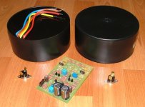
GeWa said:The PCB is just there to show the size of the transformers.
I notice another thermal breaker on the block.
Can't you at least give us simple people the specifics on those greatlooking transformers, dear Walter ?

Can't you at least give us simple people the specifics on those greatlooking transformers, dear Walter ?
Yes I can dear Jacco. They are plastic potted toroids with 2x 0-25V secondaries and rated at 500VA. I got them from RS-Components for 52,90€ each. The stocknumber is 223-8897. While I'm at it, the thermal breakers are also from RS. It's an NC type which opens at 70°C and closes again at aprox. 55°C. Stocknumber is 339-308 and costs 3,67€. I will be mounting one on each channel and connect them in series with the power switch. In the event that the heatsink, for some odd reason, would reach 70°C the whole amp will shut down. (better save than sorry)
Cheers
Attachments
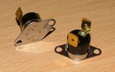
Thermal Switch
Could I put one of those bi-metal NC thermal switches in-line with the AC inlet to open up in the case of overheating? I think the equivalent is the 317-1084-ND from Digikey Page 1179 (datasheet here) which is NC and opens at 70 deg. C.
Seems like a really good idea.
Could I put one of those bi-metal NC thermal switches in-line with the AC inlet to open up in the case of overheating? I think the equivalent is the 317-1084-ND from Digikey Page 1179 (datasheet here) which is NC and opens at 70 deg. C.
Seems like a really good idea.
- Home
- Amplifiers
- Solid State
- Krell KSA 50 PCB