There is no specific reason why the drivers need to be on any heatsink with anything else
That's what I was trying to say, Q111 on the same sink as the driver transistors. Not all transistors, both driver and output, one the same heatsink. Sorry if I wasn't clear enough.
Regards
Andrew,
I use Jan's boards, the first ones, with correct traces.
About heatsinks, I will put q111 with outputs on main heatsink and drivers on separate heatsinks. I hope this 3,8 K/W will be o.k. (four heatsinks for four drivers) for 37 V rails and 1.8 A bias. If not, I can always put biger ones.
Regards
I use Jan's boards, the first ones, with correct traces.
About heatsinks, I will put q111 with outputs on main heatsink and drivers on separate heatsinks. I hope this 3,8 K/W will be o.k. (four heatsinks for four drivers) for 37 V rails and 1.8 A bias. If not, I can always put biger ones.
Regards
Neychi, driver power...
..at idle is a little less than 2w. At full power into low impedance loads this could quadruple, so you could see as much as 8w going into the driver heatsinks.
It is also proportional to the rail voltage and idle current. The figures I'm quoting are for the 37v/1.8A idle current case...
With heatsinks rated at 4c/w, you would have an increase of 32c above ambient, for a total of ~55c, hot but not too hot, so you are fine with the heatsinks you've shown us.
HTH
Stuart
Mark has made a channel or two using them, though AFAIK he is now trying out the new pinkmouse layout...
Yes, Both baords work just fine but the Pinkmouse version is ALOT more flexible and ALOT easier to deal with the driver transistors, I prefer all the heat generating devices to operate together on the main sink. If you don't want to mount the drivers on the main heatsink as I have done with both versions of the boards then with the Pinkmouse version you can do it either way..... you can leave the driver board attached to the main board and just place soome short jumpers to connect the two boards together or seperate it from the main board and have the flexibility of mounting the drivers right near the outputs. This later method keeps the wiring between boards to short lengths, not over a 4" piece of wire.
Also the advantage of having the outputs spread farther apart with Pinkmouse's board is a large advantage in dissipating the amount of heat generated.
Mark
Attachments
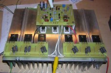
The present state of the Jan board version True Monoblock..... both drivers and bias were moved to the main sink. Extending the driver wiring this way then mounting the devices with silicon grease and then mounting the board over them was a real pain and a mess but works out well. Pinkmouse's version eliminates all the hassles of extending the drivers/bias and gives you a choice as to where and how to mount them!
Mark
Mark
Attachments


bus bars ...
In theory, yes, I agree. In practice not always the case. More ripple current you have, the greater chance of hum being injected through the grounding connection. I think it is a sound practice to always "tab off" low current (signal) grounds. Particularly if there's lots of current involved.
Copper will oxidize over time. So will brass, silver (VERY quickly!)and particularly aluminium (worst of all as Al oxide is a PERFECT insulator). One or two milliohms more is a small price to pay for a lifetime worry free connections. Besides, a larger scross section will take care of miniscule conductivity difference.
PS if you think about it, as long as you have an equal path length between the capacitors and a star grounding point, conductivity of the bus bar is absolutely irrelevant.
apassgear said:
For me, I may stress, the theoretical concept of a bus bar is one that has equal potential at any point, so installing two point star ground over it is irrelevant or the same as having only one.
In theory, yes, I agree. In practice not always the case. More ripple current you have, the greater chance of hum being injected through the grounding connection. I think it is a sound practice to always "tab off" low current (signal) grounds. Particularly if there's lots of current involved.
If I want equal potential at any point on the bus bar, cross section and material is of prime importance. So copper (or silver if I could afford it) is my first choice always. As second choice, alu or brass, but never any kind of steel which is considered a bad conductor. Of course stainless could be the material of choice when you only consider corrosion and not electrical properties.
My two cents.
Copper will oxidize over time. So will brass, silver (VERY quickly!)and particularly aluminium (worst of all as Al oxide is a PERFECT insulator). One or two milliohms more is a small price to pay for a lifetime worry free connections. Besides, a larger scross section will take care of miniscule conductivity difference.
PS if you think about it, as long as you have an equal path length between the capacitors and a star grounding point, conductivity of the bus bar is absolutely irrelevant.
Stuart Easson said:..at idle is a little less than 2w.
Doesn't this depend on the type of output device used, Stuart ?
If i look at the data of the MJL21193/4 hFe is around 90 at 0.9A bias per device.
With a couple of volts on the base of the output devices the current for the bias and the 25R resistors is already good for 4 watts of dissipation in the driver.(37PSV, 2 in parallel, 0.68R)
With 7A bias, 6 devices in parallel, i am looking at nearly 7 watts continuous dissipation for the driver.
(with the good fortune of having high hFe G-type Sanken's)
For the 25R resistors i picked Caddock style types, mounted on the heatsinks.
Did you receive the Toshiba's?
Off topic:
Neychi, some 20 years ago a lot of people experimented with plexiglass boards.
Even did it myself once,with P-T-P and wirewrapping silverwire.
Looks smashing, but sonically it doesn't outperform regular GRP boards, PTFE boards do.
Supposing you mean plexiglass with plexy, of course.
Sorry, Al.
Buss Bars - corrosion
Hi,
my school chemistry may be letting me down but I seem to recall that steel corrodes badly because the oxide products have a larger volume than the parent metal. This leads to scaling that forces the corrosion layer to separate and let more air & water onto the newly exposed surface of the parent metal causing further corrosion.
The principle for preventing this style of corrosion is to generate a corrosion layer that is stable, most often achieved by a layer that does not deteriorate and is the same volume as the parent metal.
I believe that stainless steel and chromium fall into this bracket. i.e. they both corrode to produce a very thin layer that is stable and prevents further exposure of the parent metal. Can anyone confirm this?
Can someone tell us what the conductivity of the corrosion layer is on stainless steel?
I guess it is higher than electrically clean metal.
The questions are how much higher, how effectively it can be removed, how long it stays clean, how gas tight the electrical connection can be made, what chemical application could be applied around the joint to prevent air/moisture ingress.
All your common metals whether Copper, Brass, Aluminium, Stailess steel etc. will suffer from this same surface cleanliness problem.
How do we achieve a gas tight joint?
suggestions please.
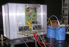
Yes, 200watt/2Ohm, already mentioned much earlier in the thread.
Per channel:
4 times 25V 300VA toroids, 6 Siemens B41564 LL 47000uF capacitors,two 2.5mH choke coils, two 0.21 C/W heatsinks with four 4.75" Papst fans, 12 Sanken 1216/2922.
Voltage regulation for the front end with two 9Vac toroidal step-up transformers.
(bought the 300va toroids by the crate at a few dollars the piece, using 8 of the same for the 10 device Leach's, and 8 for the bridged 6 device Leach's, all new identical computer types with long sleeved primaries, posted a picture of the heap at a Pass thread.)
Cant imagine the rest of the groupies going for Teflon, Al.
Price difference surprises me, raw PTFE boards are filthy expensive.
Because of that i have manufactured PTFE boards myself, try glueing copper foil on non-stick Tefal material.
The corrosion story is correct, put something with the proper PH value on stainless and you are no longer without rust.
All hardware on my boat is SS, fungus and weeds during winter produce nasty rust stains.
The corrosion layer of SS and Aluminium is much harder/less porous than the parent material.(ship construction material classes, Anno: ancient history)
Everything i make/solder i cover with plastic spray, and i prefer to solder every connection(cold sanded first) or use goldplated.
imo, bad connections are far worse than the material used.
Copper will oxidize over time. So will brass, silver (VERY quickly!)and particularly aluminium (worst of all as Al oxide is a PERFECT insulator).
Well, you can put a thin layer of anti-oxide compound on these metals and then it will not oxidize. That may be too simple though for some to grasp
") . BTW: Silver tarnishes, it doesnt oxidize.
. BTW: Silver tarnishes, it doesnt oxidize.Everything i make/solder i cover with plastic spray, and i prefer to solder every connection(cold sanded first) or use goldplated.
RCA did this to the circuit boards in the TK-76 minicam in an effoprt to waterproof them.... this was the first true portable 3 tube minicam type broadcast camera that had high resolution and such. What ever plastisizer they used sure made it VERY tough to do repairs to those boards!
imo, bad connections are far worse than the material
used.
You bet ya. Some people on this thread are way too worried about other infinatestimal things that will have such minute affects as to be unmeasurable, let alone ever audible. Now if those folks would just go build themselves a KSA-50 and get it over with........
 .
.Mark
I suppose I startred all of this discussion about steel with my pic of my P101 ground plane. I will happily change out the nuts and bolt to brass or copper next time I have it appart. I have to wonder though about those who said they use a lock washer on the conection. Aren't those made of steel and wouldn't that defeat the purpose?
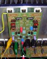
Another thing, I see in Marks post #2809 that he only mounted Q109, 110 and 111 on the main heatsink. Don't Q107 & 108 need heatsinking?
Also, can Q109 & Q110 share the same heatsink with out being insulated or would I have to use Kapton tape and plastic washers?
Thanks, Terry
Another thing, I see in Marks post #2809 that he only mounted Q109, 110 and 111 on the main heatsink. Don't Q107 & 108 need heatsinking?
Also, can Q109 & Q110 share the same heatsink with out being insulated or would I have to use Kapton tape and plastic washers?
Thanks, Terry
I have to wonder though about those who said they use a lock washer on the conection. Aren't those made of steel and wouldn't that defeat the purpose?
There are also available stainless steel star type washers as well as regular type stainless lock washers.
Also, can Q109 & Q110 share the same heatsink with out being insulated or would I have to use Kaptom and plastic washers?
Yes, they have to be insulated with what ever you prefer to use...... These devices have full rail potential on the collectors(metal tab). I use ceramic-alumnium oxide insulators on all my devices cause I can get em cheap at surplus.
Mark
- Home
- Amplifiers
- Solid State
- Krell KSA 50 PCB