PWatts said:one of the most effective solutions would be an integrated low-power switching supply
That's a very innovative idea, quite a novelty on a class A amplifier. Sounds like a good way to solve the bandwidth versus dissipation issue. I've had to raise the bias of the drivers for the KSA50 output stage considerably.
Hi,
why? to solve a problem, to meet a unique need, or something else?I've had to raise the bias of the drivers for the KSA50 output stage considerably
Okay I made the changes. The driver power can now be jumpered or separately powered by the jumpers that separate the two bottom layer copper pours, although a solid wire will probably be better. Given all the capacitance, a resistor in the region of 10-50ohms can also be experimented with if the powers are to be shared.
Conserning the decoupling arrangement, I gave the drivers one of the big electrolyitcs, an MKP and the axial cap, and added an axial cap and MKP to the rest. That should be enough capacitance and variety to please pretty much anybody.
I also changed the position of ZD1 in order to accommodate 7.5 and 15mm lead spacings for C1, and added/changed a few silkscreen things.
Lastly I fixed a serious mistake - when I changed one of the copper pours I forgot to reconnect Q17's collector
Flodstroem, either I cannot find it or P-CAD doesn't support it, but I cannot do a colour printout. The easiest would be to take the Gerber files and use a CAM viewer such as CAMTastic! or similar, where you can superimpose the layers on top of each other in the colours of your choice. We don't need a lot of people, only one with some time will do as I'm fairly certain that all is correct. Any person who's done PCB layout should have a CAM viewer. I attach the Gerber files and revised BOM.
Concerning the KMA-style regulated power supplies, I took a look at it and made some adaptions and simulations. With 5 resistors, three low-power transistors, two zeners and a number of electrolytics per rail, a very low-ripple and low-noise regulator can be built at very low cost and board space. I would however suggest that the driver and LTP sections both use their own supplies right down to the same rectifier (shared transformer secondaries should be OK, but it depends on how way-out you want to go. Even just using the main supply to subregulate will make a big difference. The mentioned circuit simulated less than 4uV ripple when I fed its incoming DC with 50 and 150Hz 4Vpp AC superimposed on it, with the amp running at full power. This is substantially less than if it's merely fed straight from the main bus with the 39V zener regulators.
We can make these regulator boards an optional part of the group buy depending on interest. It's simple enough to be built on veroboard, but will look so much more professional. Once again I suggest that it first be tested before being mass-produced, but given that it's just an enhancement of the original it shouldn't be a problem.
If I have time I can also try to evaluate the LM5007 500mA switching regulator as a pre-regulator for the whole story; it's a small 8-pin chip and only needs a few small external components. The 500mA capability should be more than enough, but I'll check for beefier ones to accommodate people who'd want to experiment with higher driver bias.
The only part that will take a little more space is the voltage bus for the incoming DC; but even that will not be too large is a smallish bank of 470uF caps as in the original is used. A small 20VA or so transformer and two of these boards per channel will offer signifantly cleaner supplies, at very low cost since all the components can be cheap. The big capacitors offered on the main board means that no big post-filtering caps on the regulator boards are necessary.
Attachments
No problem with shunt regulators besides that they're very inefficient - OK to use for the LTP but maybe a little impractical for the drivers. But, depending on the interest it could be included.
The LM2951 seems to be a good choice as preregulator, 150kHz switching frequency and 1A current ability. Otherwise a LM317 would also work, but the switching regulator will be much more efficient in dropping the voltage with less dissipation and thus a smaller required transformer. Its 150kHz switching frequency will also lead to a very clean DC output especially after the rigorous subsequent regulation and filtering.
The LM2951 seems to be a good choice as preregulator, 150kHz switching frequency and 1A current ability. Otherwise a LM317 would also work, but the switching regulator will be much more efficient in dropping the voltage with less dissipation and thus a smaller required transformer. Its 150kHz switching frequency will also lead to a very clean DC output especially after the rigorous subsequent regulation and filtering.
The fact that Dan The Man prefered the KMA-100 to the KSA-100 tells me that the old power supply is still a good place to start. Sure it's old but lets face it... it does make an improvement that people on this thread have reported hearing and... its VERY INEXPENSIVE to build! I think a seperate power supply thread is a good idea and those knowledgable in power supply design might want to start one. But for now please lets ust keep this thread going forword so we can get the boards made and at least one amp up and running to prove the board.
Mark
Mark
Indeed the KMA is a good place to start. The changes I made is very subtle and not at all a major change; mainly it's actually just some of the capacitor values since modern capacitors are so much smaller than back then.
The pre-regulator is just to keep the actual regulator stage smaller since they'll have less to dissipate and thus a lighter load on the transistors; This will be especially good if we use separate DC boards and regulator boards; this will have to be decided.
The idea of using totally separate supplies for the driver and LTP stages instead of subregulating one from the other is IMO so simple and cheap that it will be a good idea. With compact layout it can still be made very small, and once again reduce the load on the transistors.
The pre-regulator (if used, but the reasons mentioned makes it very attractive - it wasn't used back then since these things didn't exist) can either be a vanilla LM317 with a small heatsink to allow the rest to have a light load, or the switching regulator that will produce a much cleaner and 50Hz-free output and dissipate much less power and thus require a smaller transformer. It's only a TO-220 package, three resistors, a capacitor and a small choke, so it can easily be bypassed. I can make the boards that they support both that regulator, the LM317 or none.
I'll still do some further simulations to determine the optimal configurations without wasting capacitor space, but for the time being the bunch of electrolytics will take up 90% of the space.
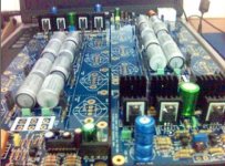
OK I have two KSA's in my possession right now (MK1 and MK2), courtesy of Jozua. Interesting enough the spectra of the MK1 (haven't measured up the MK2 yet as I still have to rewire its 110V transformers to 220V) is not as good as the KSA50 clone I built. Higher noise floor and considerably higher 50Hz ripple. I did notice that the effect of those 10ohm resistors between ground and safety ground has a large influence on the 50Hz ripple as one would expect. Rip them out if you can.
I also saw a few other interesting things; one of which is that there appears to be a fifth version of the amp. The drivers use BD911/BD912, and some of the other TO220 packages are 2N655 something; they are too faint to read.
The other is that the boards are different dimension-wise. Width and height is within 2mm of selchuk's measurements, but the bottom mounting hole is a full 31mm lower than on the Mk2; almost at the very bottom. So I'll just add two extra mounting holes for MK1 compatibility; after all MK1 owners will have the most to gain from the upgrade with the new boards.
I'll take some pictures after I'm done with the modifications, sine the Mk2's boards have to come out for service (mainly BG a upgrade) which will allow nice & closeup pictures.
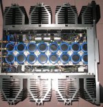
Krell definitely began to get their act together on the Mk2 - almost everything that seemed a little "geez that's skimpy/pennypinching for such a high-end amp" on the Mk1 has been beefed up on Mk2. Of course there are always areas that could've been better but all in all the quality level has been shifted up a notch. A few differences are:
- The Mk2's power transformers are considerably larger than the Mk1's. Perhaps only the pots are bigger, but since the Mk2 is a bit heavier it's possible that Krell decided to up the juice.
- The 10R resistors to safety ground has been changed from cheap carbon types to Dale 5W
- The output transistors is newer
- The driver heatsink is 55% wider, partly to accommodate the extra drivers. Since the dissipation is more or less the same, the MK1's get damn hot.
- the wiring overall is thicker: DC, speaker, even the hookup wire on the output stage
- The fans (mounted on top on the Mk1) is nice and sturdy metal fans; on the Mk1 they're no-name plastic stuff
- Krell were somewhat neglictic with the fuses - they used the same 12A fuse on both the 110V and 220V versions
- The RCA connectors are a bit higher quality
- The capacitor for the zobel network is a bit better quality, and better housed than the afterthought exposed method on the Mk1
- They ditched some of the excessive protection of the MK1 (mainly because the MK2's protection was better): DC and loudspeaker fuses at the backpanel which meant a lot of extra wiring. Funny is that they only used a DC fuse for the positive rail though.
- The overall wiring layout is neater despite being more complex on the Mk2
- The Mk1's soft-start thermister (obviously absent on the Mk2) is too small and gets way too hot.
")
- Home
- Amplifiers
- Solid State
- Krell KSA 100mkII Clone