Here's the wiki for the KSA-50, which is very similar to the 100, lots of good info:
Krell KSA-50 clone Building Guide - diyAudio
Krell KSA-50 clone Building Guide - diyAudio
Try if you can order from Fischer
Here`s the link:
LA 1 ..., Segment cooling aggregates, Heatsinks f.cool, Fischer Elektronik
All I need to finish my KSA-100 are a set of fan type heat sinks. Even FIX is out of them. I found these on ebay but wonder if they are big enough.
1pcs Aluminum Heatsink for Amplifier ?Fan Type 300mmx93mmx63mm | eBay. Suggests anyone?
Here`s the link:
LA 1 ..., Segment cooling aggregates, Heatsinks f.cool, Fischer Elektronik
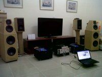
Speakers
Love those speakers. I feel I might need them for my Krell clone. Can you share it history (your building them).Another Krell clone is born......
Well it has been a while since I have been around. i still have my PH Watts boards and am now in a position to finally build them. Unfortunately, the wiki doesn't seem to be there any longer. I don't suppose someone saved a copy of it before it was killed? Even a copy of the BOM would be helpful.
Thanks, Terry
Thanks, Terry
Well it has been a while since I have been around. i still have my PH Watts boards and am now in a position to finally build them. Unfortunately, the wiki doesn't seem to be there any longer. I don't suppose someone saved a copy of it before it was killed? Even a copy of the BOM would be helpful.
Thanks, Terry
Hi Terry,
There is this info here if it can help:
diyAudio.com Wiki - projects by fanatics, for fanatics
There is also a KSA-100 built with another board here, there might be some interesting information as well.
http://www.diyaudio.com/forums/solid-state/183562-ksa-100-jims-audio-ebay.html
I also have a few useful info I could send you, such as pictures, BOM, schematic, send me a pm if you need something.
Cheers,
")
Eric
Well it has been a while since I have been around. i still have my PH Watts boards and am now in a position to finally build them. Unfortunately, the wiki doesn't seem to be there any longer. I don't suppose someone saved a copy of it before it was killed? Even a copy of the BOM would be helpful.
Thanks, Terry
Hi Terry!
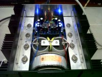
I have built 8 boards now. Two boards that was tested. First by an original power supply, ± 52-54V and another wit a regulated power supply for the drive board.
Some interesting data:
With an original power supply the power output was measured to be >120W in 8 ohm and approx 200W in 4 ohm (right before clipping)
Then I made a test with my new power supply for the drive board fed by regulated ±63V (power stage was still fed by the ± 52V supply)
Power output was then raised to 170W in 8 ohm and as much as 300W in 4 ohms. A huge improvements compared to the original power supply.
No other measurements was done in this case, but the signal locked fine, eg. the same as by the original power supply. Bias current was set to approx 525-550 mV (eg. 0.52-0.55A through the emitter resistors). I used 4 complimentary pairs, same as in the original amp.
The amp is not yet in the condition for to check the sound by my JBL speakers.
Also, check post 2556, there you have some pictures of when I tested the drive boards.
Last edited:
Thanks a lot guys. Man I was shocked when I saw that the wiki was gone. A thread that big and they killed the wiki. Looks like someone started a new so that should be good enough. I haven't decided whether or not to use TO3 or plastic yet. I am contemplating stripping my Aleph-X and doing a passive unit with plastic devices. I've never been satisfied with the AX and that huge coffin might make a nice KSA. I already have two KSA 50's, one with TO3 and one with MJL4281/4302. I have plenty to go either way. The plastics are enticing because I won't need tunnels or fans. I might go down a little in rail voltage too. Don't you just love DIY?
The regulated supply looks interesting too. I did that on my Low TIM.
Thanks, Terry
The regulated supply looks interesting too. I did that on my Low TIM.
Thanks, Terry
Thanks a lot guys. Man I was shocked when I saw that the wiki was gone. A thread that big and they killed the wiki. Looks like someone started a new so that should be good enough. I haven't decided whether or not to use TO3 or plastic yet. I am contemplating stripping my Aleph-X and doing a passive unit with plastic devices. I've never been satisfied with the AX and that huge coffin might make a nice KSA. I already have two KSA 50's, one with TO3 and one with MJL4281/4302. I have plenty to go either way. The plastics are enticing because I won't need tunnels or fans. I might go down a little in rail voltage too. Don't you just love DIY?
The regulated supply looks interesting too. I did that on my Low TIM.
Thanks, Terry
Hi Terry, just curious about the two you have built. Is there any substantial difference between plastic and TO3 transistors?
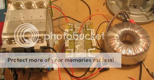
Not that I can hear. If I switch from amp to amp they are pretty much identical. I prefer the design of the one with the TO3's. For the plastics I put two flat panel heatsinks fin to fin to create a sort of tunnel. This pic is how I intended to do it but it was too tall so I stood that on end in the center of my case with a hole in the bottom under the sinks then put the fans in the back panel blowing air out of the case. This forces the air to be drawn in the bottom of the sinks. I think the sinks get enough air but the case gets really hot for all the hot air coming out of the sinks.
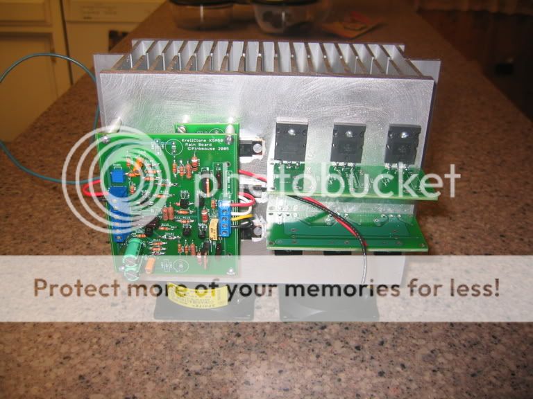
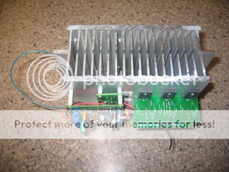
Here's a picture of the TO3 model sans the case.
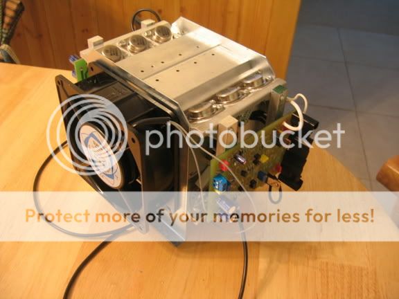


Here's a picture of the TO3 model sans the case.


Can i use these cap`s:
F&T 47000µF Electrolytic Capacitor 63V
seems they dont have 75V
47000µF Electrolytic Capacitor 63V % F & T GMB47306365100 from Conrad.com
F&T 47000µF Electrolytic Capacitor 63V
seems they dont have 75V
47000µF Electrolytic Capacitor 63V % F & T GMB47306365100 from Conrad.com
no dont use them,unless you choose carefully capacitance and deviation to be within 1000uF and not more.
You need 75-100v capacitors,dont be greedy consider multiplying your tested AC x 1.42 i receive 242 VAC from wall and it gets up to 250 ,even 1 volt above capacitor maximum rating can damage it ,and use self healing capacitors soldering them with SnCu and Silver .
Heal the capacitors before soldering them with low voltage(10-25V) for 10-15 minutes -connect them all in series ,let them discharge by itself
-use some copper or aluminium wire to tie
also a good advice -dont use bridge rectifier use Ultrafast switching schotkky there are some with 35ns recovery and low drop,very smart
Last edited:
The Krell Klone runs on raoughly +-52Vdc.
Adding on 6% for highest mains supply voltage brings this up to ~+-55Vdc
If the bias is turned down a lot or the amps blow the secondary fuses after the smoothing capacitors, then the voltage will rise much higher, possibly rising a further 5V to end up with a worst case +-60Vdc.
63V capacitors are rated for 63Vdc. They are no problem on a Krell Klone running @ +-52Vdc.
Hi all,
I still have the KSA-100 prototype around here from way back when we started this thread.... I have always had too large of a power transformer in mine and I have to run it down to the nominal +-52 volts with a 20 amp variac to be able to operate the amp.
Without having to go back through and read a gazillion posts what power transformers is everyone using to build these amps? Is there anything decent available "off the shelf" that will get me within a few volts of the correct rails so I don't have to resort to a custom transformer? Now that I have the time I would like to finish mine in the very near future...
Thanks,
Mark
- Home
- Amplifiers
- Solid State
- Krell KSA 100mkII Clone