Ni Hao Ma?
I think that you have just returned back from your HAPPY Xin Nian holidays.
Tks for the comment. I am going to drive my F1 power amp. Shi de . . . the output impedance has been one of my questions. The reason of the high Rd of 1.5K is to set the DC on about 37V at the Drain with the bias current of about 15mA, which is assumed after taken into a consideration of power dissipation rate of J310.
Maybe, we could kindly ask Nelson whether this high impedance is still okay . . . Are you there Nelson . . . ?
I have just received a number of J310 from my order. As soon as I return (too), I could measure them and could readjust the bias current and the size of Rd in the course of construction. I will inform you later . . .")
Regards
jh
I think that you have just returned back from your HAPPY Xin Nian holidays.
Tks for the comment. I am going to drive my F1 power amp. Shi de . . . the output impedance has been one of my questions. The reason of the high Rd of 1.5K is to set the DC on about 37V at the Drain with the bias current of about 15mA, which is assumed after taken into a consideration of power dissipation rate of J310.
Maybe, we could kindly ask Nelson whether this high impedance is still okay . . . Are you there Nelson . . . ?
I have just received a number of J310 from my order. As soon as I return (too), I could measure them and could readjust the bias current and the size of Rd in the course of construction. I will inform you later . . .
Regards
jh
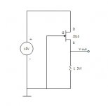
Tested J310 as shown.
Since I had available V of 15V only, I use it as Vd.
Sampled 54 x J310.
Found that 22 of them had Vgs of -30mV and the remaining 32 had -27~-29mV.
Max. Ids of 30mA each . . .
Too small . . . I want to have bias of about 20mA . . . hmm . . .
Only solution is paralleling?
Your opinion, tks . . .
Regards
jh
Attachments
jh6you said:Tested J310 as shown.
Since I had available V of 15V only, I use it as Vd.
Sampled 54 x J310.
Found that 22 of them had Vgs of -30mV and the remaining 32 had -27~-29mV.
Max. Ids of 30mA each . . .
Too small . . . I want to have bias of about 20mA . . . hmm . . .
Only solution is paralleling?
Your opinion, tks . . .
Regards
jh
looking at attachment from your post No.19
you'll have more like 15mA per Jfet,not 20...or you just change your mind?
take care about max dissipation ,not just current through Jfet
in case that you choose paralleling,put separate grid and source resistors (local degeneration) ;they have same purpose as in output stages for biiigguns

edit:
say-22 ohms for gates, 47 ohms for sources
When I write on the computer, I usually enjoy Zennheizer headphone . . . I am listening to Lou Reed, and feeling sleepy . . . 15mA . . . 20 mA . . . yee . . . 15mA !! . . . 
I have thought I can not have the source resisitor to my circuit . . . Tks, will think about again if the source resistor is acceptable . . . time to go to zzzzzzzzzz . . .
Regards
jh
I have thought I can not have the source resisitor to my circuit . . . Tks, will think about again if the source resistor is acceptable . . . time to go to zzzzzzzzzz . . .
Regards
jh
jh6you said:When I write on the computer, I usually enjoy Zennheizer headphone . . . I am listening to Lou Reed, and feeling sleepy . . . 15mA . . . 20 mA . . . yee . . . 15mA !! . . .
I have thought I can not have the source resisitor to my circuit . . . Tks, will think about again if the source resistor is acceptable . . . time to go to zzzzzzzzzz . . .
Regards
jh
next time use something from early Bowie
same stuff,but you can't sleep....
Choky again:
if you parallel Jfets,each must have dedicated source resistor-same as output mosfets in any Aleph...........
if you use just one Jfet,than you don't need any stinking resistor in source
short data for J310?
My head seems to be recovered after staying many hours away out of Lou Reed’s incantation . . . . . . Ah yeah . . . the source resistors . . .
For the self-bias of JFET, the source R is essential to set up the bias current and the corresponding Vgs. In contrast, I adopt the CCS-bias and a fixed Vg being injected from the outside world without having any source R. To this, if I add a source R, it would be considered as a combined bias system with both the CCS- and the self-. The CCS-bias would try to fix a Vgs at one point while the source R would try to change it. O! no . . . my head is again gonna be getting dizzy . . .
 . . . I like the philosophy of the-simpler-the-better . . . due to the limitation of my brain activity . . . Oops! . . . but, it’s true . . .
Often, I call my second son a blue frog, who never jumps when I say, jump, and always jumps when I say, freeze . . . Meanwhile, his mother likes to remind me that he does not resemble her . . . Hmm . . . the data sheet of J310 says that the drain current is an inverse proportion to the temperature . . . Isn’t this good enough to assure no phenomena of thermal runaway in case two JFETs are paralleled without any source R? Arrrrrrrh . . . I need to read more . . .
Regarding power dissipation, inform you that the circuit will provide Vds of about 6V across J310.
Regards
jh
. . . Ah yeah . . . the source resistors . . .For the self-bias of JFET, the source R is essential to set up the bias current and the corresponding Vgs. In contrast, I adopt the CCS-bias and a fixed Vg being injected from the outside world without having any source R. To this, if I add a source R, it would be considered as a combined bias system with both the CCS- and the self-. The CCS-bias would try to fix a Vgs at one point while the source R would try to change it. O! no . . . my head is again gonna be getting dizzy . . .
. . . I like the philosophy of the-simpler-the-better . . . due to the limitation of my brain activity . . . Oops! . . . but, it’s true . . .Often, I call my second son a blue frog, who never jumps when I say, jump, and always jumps when I say, freeze . . . Meanwhile, his mother likes to remind me that he does not resemble her . . . Hmm . . . the data sheet of J310 says that the drain current is an inverse proportion to the temperature . . . Isn’t this good enough to assure no phenomena of thermal runaway in case two JFETs are paralleled without any source R? Arrrrrrrh . . . I need to read more . . .
Regarding power dissipation, inform you that the circuit will provide Vds of about 6V across J310.
Regards
jh


Hi, Choky
I am now getting nervous leaving D-2. Kindly allow me to smoke your last cigarette.
I WILL use a source resistor even if I use a single JFET. I took out a torch light and once again searched the sight more carefully. Yes, there is a stage wide enough in-between the JFET Source and CCS MOSFET Drain where one source resistor can dance. I have two main reasons why I am going to have the source resistor (as I thought at the beginning of the project).
I would like to compromise the voltage gain.
And, when I use J310, I estimate from the data sheet that I could have Vgs swing only within about +/-1V (in comparison with the swing of the input signal of about +/-2V). This means that I want to have a source resistor of about 68R (in case of single JFET) in case of 15mA bias.
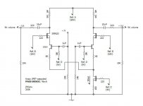
Accordingly, I attach another revised schematic.
Should I have a Gate resistor too . . . ?
Do you have any further comment . . . ?
Thanks.
Regards
jh
PS. I was wrong. The Vds across JFET will be about 4V.
I am now getting nervous leaving D-2. Kindly allow me to smoke your last cigarette.
I WILL use a source resistor even if I use a single JFET. I took out a torch light and once again searched the sight more carefully. Yes, there is a stage wide enough in-between the JFET Source and CCS MOSFET Drain where one source resistor can dance. I have two main reasons why I am going to have the source resistor (as I thought at the beginning of the project).
I would like to compromise the voltage gain.
And, when I use J310, I estimate from the data sheet that I could have Vgs swing only within about +/-1V (in comparison with the swing of the input signal of about +/-2V). This means that I want to have a source resistor of about 68R (in case of single JFET) in case of 15mA bias.
Accordingly, I attach another revised schematic.
Should I have a Gate resistor too . . . ?
Do you have any further comment . . . ?
Thanks.
Regards
jh
PS. I was wrong. The Vds across JFET will be about 4V.
Attachments


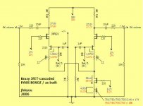
Thank you very much, Nelson, for your inspiring me into this Krazy. 
Oh . . . and thank you, Choky, for your inspiring me with the PSU . . . . . . By the way, I changed two resistor values to come closer to the necessary voltages . . .
Here is the schemetic as-built. The blue figures from the L-channel and the red from the R-channel. It works very well . . . better than I expected . . .
Sound . . . ? The tooboo guy could have ANOTHER pair of jades . . .
Try it when you are ready to do . . .
jh
Oh . . . and thank you, Choky, for your inspiring me with the PSU . . .
. . . By the way, I changed two resistor values to come closer to the necessary voltages . . .Here is the schemetic as-built. The blue figures from the L-channel and the red from the R-channel. It works very well . . . better than I expected . . .
Sound . . . ? The tooboo guy could have ANOTHER pair of jades . . .
Try it when you are ready to do . . .
jh
Attachments
jh6you said:
Here is the schemetic as-built. The blue figures from the L-channel and the red from the R-channel. It works very well . . . better than I expected . . .
Sound . . . ? The tooboo guy could have ANOTHER pair of jades . . .
Try it when you are ready to do . . .
jh
oh,man-I already have muucho line stages....
but-there is not such thing as redundant line stage
who knows....
anyway-I'll sit these dayz and make one shunt reg proposal to ya , yinyang boy..........
now is time for cup of sake ?
wine
bear?
and one good ciiiiiigar........
Hi, Steen
Intersted in the sound of Krazy, aren't you . . . ?
And, I remember (by a picture somewhere) that you have Tracy Chapman . . .
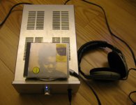
Many people like to use their reference systems whenever they evaluate new sounds . . . Yeah, I am not an exception . . . You know . . . ? My reference system is a Sennheiser headphone and a phone amplifier. For your info - my phone amplifier is made of all tubes including for supply voltage regulation . . . Might be too poor to be a reference . . . . . .
Music through Krazy BOSOZ (& F1 & J-low) gives me very similar taste to my reference system . . . I can't say which one is better because I can't directly compare my J-low system with the headphone system. . . Both are very good, I'd like to say so . . .
If you have any chance, try to build one, the same one or similar one you like to try . . . I dare to say, the music lover will not be disappointed . . .
Regards
jh
Intersted in the sound of Krazy, aren't you . . . ?
And, I remember (by a picture somewhere) that you have Tracy Chapman . . .
Many people like to use their reference systems whenever they evaluate new sounds . . . Yeah, I am not an exception . . . You know . . . ? My reference system is a Sennheiser headphone and a phone amplifier. For your info - my phone amplifier is made of all tubes including for supply voltage regulation . . . Might be too poor to be a reference . . .
. . .Music through Krazy BOSOZ (& F1 & J-low) gives me very similar taste to my reference system . . . I can't say which one is better because I can't directly compare my J-low system with the headphone system. . . Both are very good, I'd like to say so . . .
If you have any chance, try to build one, the same one or similar one you like to try . . . I dare to say, the music lover will not be disappointed . . .
Regards
jh
Attachments

- Status
- This old topic is closed. If you want to reopen this topic, contact a moderator using the "Report Post" button.
- Home
- Amplifiers
- Pass Labs
- Krazy JFET-cascoded Pass BOSOZ