It looks interesting; I particularly like the low voltage requirements (which also means low power supply costs) so to a certain respect that mitigates the cost factor compared to other more conventional glass solutions.
The microphonic nature is the real issue as far as I see. I am sure Korg or Noritake Itron are working on that aspect as we speak. For now, I am going to pass but will keep my eye on things going forward.
I wish you good luck pmillet; I hope this works out for you. I hope that the issues with regard to the microphonic nature can be solved or at least the resonant frequency can be pushed out of the audio band perhaps. Maybe even a tight Q filter could be implemented; some times a notch filter isn't as noticeable as you might at first assume. 5.8 KHz is up there a bit already.
Maybe soon ...
I am working on a few reference schematics. Also an article is upcoming in audioXpress. It's pretty simple.
You typically need some kind of buffer on the input to drive the grid. I have used both a JFET buffer, and a small MOSFET follower. Either works well. If the input impedance of the class D amp is low (10's of K) you also need an output buffer - same idea, JFET or MOSFET.
I am attaching the schematic of the entire class-D hybrid amp I built (shown below). I used dual JFETs to buffer in and out, and a JFET phase splitter to drive complementary inputs to the class D. This preformed better than driving it single-ended.
Pete
Are you considering building and selling boards for the Class D hybrid amp, Pete? This could be a fantastic way to spread the 6P1 love. I'd probably be one of the first buyers!
-D
I don't see the microphony as being a huge drawback. It just needs to sit on a firm, non-vibrating surface. Guitar combo amps wouldn't be good. EF86s have the same problem.
Sent from my phone with Tapatalk. Please excuse any typpos.
Music Amp and portable / automotive applications are exactly what I would use them for because of the power requirements. For an AC powered application I'd still use glass.
Are you considering building and selling boards for the Class D hybrid amp, Pete? This could be a fantastic way to spread the 6P1 love. I'd probably be one of the first buyers!
-D
Maybe.
The one I built uses a lot of surface mount components. So it would have to be an assembled module. And I'm not sure I want to do that...
I thought about re-designing it to be all through hole except the class-D chip, then selling the board with the IC mounted. But I'm still undecided if it would sell enough to be worthwhile.
Pete
Well, if you change your mind.

You could make a very interesting integrated amp with optional headphone output by combining your hybrid headphone amplifier + class-D amplifier. Mount the components other than the 6P1 on the back side of the boards and mount the boards flush to the front or top panel with appropriately-sized cutouts so you could see the electrons a-flowin'.
-D
Last edited:
Well, if you change your mind.
You could make a very interesting integrated amp with optional headphone output by combining your hybrid headphone amplifier + class-D amplifier. Mount the components other than the 6P1 on the back side of the boards and mount the boards flush to the front or top panel with appropriately-sized cutouts so you could see the electrons a-flowin'.
-D
And someone has already done something like this (at least visually).

-D
I now have Pete's nutube headphone amp built.
One question is on the biasing (note I am a beginner with tubes).
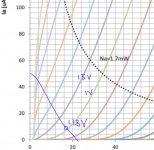
The nutube datasheet spec says max Grid voltage is 5.0V and Bias voltage max 3.5V, yet in the user manual says bias to 11V (24V supply).
Can anyone explain the reason for the 11V bias?
I looked at the curves and grid voltage only shows up to 4V , I would assume the optimal would be within those curves voltages.
One question is on the biasing (note I am a beginner with tubes).
The nutube datasheet spec says max Grid voltage is 5.0V and Bias voltage max 3.5V, yet in the user manual says bias to 11V (24V supply).
Can anyone explain the reason for the 11V bias?
I looked at the curves and grid voltage only shows up to 4V , I would assume the optimal would be within those curves voltages.
I now have Pete's nutube headphone amp built.
One question is on the biasing (note I am a beginner with tubes).
The nutube datasheet spec says max Grid voltage is 5.0V and Bias voltage max 3.5V, yet in the user manual says bias to 11V (24V supply).
Can anyone explain the reason for the 11V bias?
I looked at the curves and grid voltage only shows up to 4V , I would assume the optimal would be within those curves voltages.
I haven't looked at the circuit in question, but with a tube, the grid bias referenced in the datasheet is the difference between the voltage on the grid and the voltage on the cathode. My guess is, again without looking at the manual, is the 11v is cathode to ground, and if you measured the voltage on the grid would be 8.5v or 9v giving a grid bias of -2 to -2.5 volts or something within the tolerance stated in the datasheet.
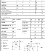
Here is the datasheet. http://www.nutube.us/downloads/Nutube_Datasheet_31.pdf
Nutube user manual
http://www.pmillett.com/file_downloads/NuHybrid_assy.pdf
Nutube user manual
http://www.pmillett.com/file_downloads/NuHybrid_assy.pdf
Attachments
I haven't looked at the circuit in question, but with a tube, the grid bias referenced in the datasheet is the difference between the voltage on the grid and the voltage on the cathode. My guess is, again without looking at the manual, is the 11v is cathode to ground, and if you measured the voltage on the grid would be 8.5v or 9v giving a grid bias of -2 to -2.5 volts or something within the tolerance stated in the datasheet.
Sorry, my mistake. Measure the wrong pins. With 22V input and 11V bias.
Grid ref to ground is 1.87V, ref to Cathode would be -0.7v or 1.17V
I now have Pete's nutube headphone amp built.
One question is on the biasing (note I am a beginner with tubes).
The nutube datasheet spec says max Grid voltage is 5.0V and Bias voltage max 3.5V, yet in the user manual says bias to 11V (24V supply).
Can anyone explain the reason for the 11V bias?
I looked at the curves and grid voltage only shows up to 4V , I would assume the optimal would be within those curves voltages.
The manual says to adjust the grid bias to get 11V on the test point, which is on the plate of the tube - not the grid.
The grid bias adjustment range is 0V to +3.3V.
Biasing at 11V on the plate results in nearly the lowest distortion, when operating on a 24V supply, with this load resistance.
Pete
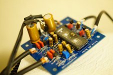
Pete's headamp - PCB with 6P1 plus the kit
Hi everyone.
I got my kit, the PCB and the tube last Thursday (found them at my door when I came from work.. ups). I spent the night soldering the components but I stopped before the last step, the tube. It was 12:30 AM and I didn't want to s...w up anything.
Friday I debated with myself for about 2 hours if and how I should mechanically isolate the tube from the PCB to avoid microphony. Ended up following the instructions and just used the foam pads that came with the tube.
Everything went smooth and I have been able to set the bias to 11 V (on the test points), as indicated in the instructions.
I have to say that if one follows the instructions there should be no issues. You need a little bit of soldering experience, though, since some of the pads are really small.
Some background about this project: I am a dedicated to solid state guy and I have never before tried any tube based build. I do understand the technical aspects and I love fidelity (meaning what's coming in should go out). I also understand someone’s preference for a certain thing (when it comes to personal taste there should be no discussion). That being said I wanted to experience firsthand the tube "flavor" and, eventually, understand the appeal. Since this project was more of an experiment I just followed the instructions and made no changes.
The bad:
- The 3.3 V regulator for the filament really gets hot. So hot that I wouldn't use it for a long time (it worked for a couple of minutes but I didn't want to push it longer) without a heat sink.
- Microphony is there, very real. You touch the board, you get the ping. I even experienced some positive feedback from speakers with a little bit of oscillation. Once you touch the tube to dump the vibration it goes away. I had to "hide" the PCB behind the amp, directly on a rigid surface. Once I have done that there was no positive feedback any more.
The good:
- The PCB along with the tube arrived much quicker than estimated by EBay (3-4 days)
- The kit provided by Mouser was complete and all the components fitted perfectly. This one arrived even quicker.
- Everything went smooth, as described in the very detailed instructions provided by Pete (thank you).
- When you get to the "Now listen" part of the instruction that's it, you can listen.
- With a short on the inputs it is quiet (I wasn't able to hear anything with my ear near the speaker - once there was no oscillation)
- The sound was really good. Unfortunately I have no technical terms and/or numbers since I have made no tests and took no measurements (other than the bias). The only way I can describe it: smooth and sweet.
On the gray part (I don't know if this should be classified as good or bad - I take it as tube experience): if you are looking for very crisp highs they are not there. I have compared with solid state and the highs are somehow softer.
I have listened to a plethora of music types to experience the results (my usual soft vocal jazz but also disco, club, electronic, symphonic, opera, pop, rock, and some hard to categorize, not necessarily in this order.
My conclusion (this is personal opinion/taste and so.. see above): I came to like the feeling given by this little tube based preamp/headamp. It really performed impressively with all the music I have listened to. Jazz and vocal in general got the most benefits but also delivered the disco and club punch, the fullness of symphonic. I didn't expect as much as I got for electronic music. Listened to some Kraftwerk and I liked it!
I know it's not pure tubes and most likely it can get better but it really made me curios and I will, probably, try some more in the future (maybe a "pure tubes" one).
Thank you Pete, I hope this helps.
Cornel
Hi everyone.
I got my kit, the PCB and the tube last Thursday
(found them at my door when I came from work.. ups). I spent the night soldering the components but I stopped before the last step, the tube. It was 12:30 AM and I didn't want to s...w up anything.Friday I debated with myself for about 2 hours if and how I should mechanically isolate the tube from the PCB to avoid microphony. Ended up following the instructions and just used the foam pads that came with the tube.
Everything went smooth and I have been able to set the bias to 11 V (on the test points), as indicated in the instructions.
I have to say that if one follows the instructions there should be no issues. You need a little bit of soldering experience, though, since some of the pads are really small.
Some background about this project: I am a dedicated to solid state guy and I have never before tried any tube based build. I do understand the technical aspects and I love fidelity (meaning what's coming in should go out). I also understand someone’s preference for a certain thing (when it comes to personal taste there should be no discussion). That being said I wanted to experience firsthand the tube "flavor" and, eventually, understand the appeal. Since this project was more of an experiment I just followed the instructions and made no changes.
The bad:
- The 3.3 V regulator for the filament really gets hot. So hot that I wouldn't use it for a long time (it worked for a couple of minutes but I didn't want to push it longer) without a heat sink.
- Microphony is there, very real. You touch the board, you get the ping. I even experienced some positive feedback from speakers with a little bit of oscillation. Once you touch the tube to dump the vibration it goes away. I had to "hide" the PCB behind the amp, directly on a rigid surface. Once I have done that there was no positive feedback any more.
The good:
- The PCB along with the tube arrived much quicker than estimated by EBay (3-4 days)
- The kit provided by Mouser was complete and all the components fitted perfectly. This one arrived even quicker.
- Everything went smooth, as described in the very detailed instructions provided by Pete (thank you).
- When you get to the "Now listen" part of the instruction that's it, you can listen
.- With a short on the inputs it is quiet (I wasn't able to hear anything with my ear near the speaker - once there was no oscillation)
- The sound was really good. Unfortunately I have no technical terms and/or numbers since I have made no tests and took no measurements (other than the bias). The only way I can describe it: smooth and sweet.
On the gray part (I don't know if this should be classified as good or bad - I take it as tube experience): if you are looking for very crisp highs they are not there. I have compared with solid state and the highs are somehow softer.
I have listened to a plethora of music types to experience the results (my usual soft vocal jazz but also disco, club, electronic, symphonic, opera, pop, rock, and some hard to categorize
, not necessarily in this order.My conclusion (this is personal opinion/taste and so.. see above): I came to like the feeling given by this little tube based preamp/headamp. It really performed impressively with all the music I have listened to. Jazz and vocal in general got the most benefits but also delivered the disco and club punch, the fullness of symphonic. I didn't expect as much as I got for electronic music. Listened to some Kraftwerk and I liked it!
I know it's not pure tubes and most likely it can get better but it really made me curios and I will, probably, try some more in the future (maybe a "pure tubes" one).
Thank you Pete, I hope this helps.
Cornel
I just finished the buffer and so far have tried it connected to my ACA and my M2 and even my car (too much gain there, will have to work on that). Haven't done a lot of A/B comparison but so far I like the sound. I still have to fine tune the bias (someday I need to get a scope). Right now I'm running it off 5V to get the minimum gain. It is just rough wired to connectors right now as it needs a case and I'd like to add a decent switch that would allow it to bypass the buffer when the power is switched off. And it would be cool to find a case that allowed the nutube to show
Attachments
I just couldn't resist the blueish glow and placed an order for the NuHybrid headphone amp! I think the price is a real bargain, because the pcb is included together with the tube. Thanks to Mr Millett for providing this.
I would very much like to make the tube glow visible via some kind of opening in the front plate, but it might be tricky with the board provided. Something like in post #67 Let's see what I can make out of it...
I would very much like to make the tube glow visible via some kind of opening in the front plate, but it might be tricky with the board provided. Something like in post #67 Let's see what I can make out of it...
- Status
- This old topic is closed. If you want to reopen this topic, contact a moderator using the "Report Post" button.
- Home
- Vendor's Bazaar
- Korg NuTube is now available online