Hey all,
It's been a while, but I'm getting back into the audio game again with a Uniamp from Pete Millet's wonderful website.
I am building this for a friend so I'm trying for a showroom quality build here, but given my track record, some blemishes may arise which we will call "character" from here out, OK?
So, I've attached my BOM for your review. I didn't think too long about it, I just ordered what I thought was right, putting some extra cash into the coupling caps and some key resistors and keeping the other parts somewhat down to earth. I have been known to over-buy in some areas, but I tried to reel it in here where I felt I could.
Transformers will be Edcor (10 week lead time!) with the recommended Sowters pulling the phase-splitting duty. I ordered some pre-made chassis here. These looked cool in the photo and should be plenty big enough for each monoblock. I'll report on these once I have them in hand (maybe late this week or early next).
I have some questions about the power supply that I'll pose in a subsequent post. Let me know if you think the BOM is wacky in some way.
Here we go!
Kofi
Attachments
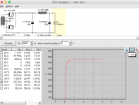
So, regarding the PSU. Per Pete's calculations, the KT88s will run at 78mA with a couple of 6SN7s for voltage amplification. i called that about 100mA and ran some Duncan PSUD2 simulations with the 400-0-400 transformer and a 5U4-GB rectifier.
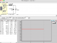
I can't get anywhere near the 370V B+ that Pete references. With a 47uF cap input, I get about a 460V B+. Changing to a choke input, I get about a 330V B+. I've attached shots from PSUD for review.
I've been married long enough to know that this is somehow my fault. What am I doing wrong?
Any guidance would be appreciated.
Kofi
Attachments
Have you tried shrinking that input cap down? Start at 1u and see what happens. 47u seems large for a 5u4 anyway.
Thanks!
1uF gets me to about 350V, 2uF gets me about 410V, 1.5uF gets me about 386V. Looks like maybe I just need to play with the lower values until I lock in the right B+.
Alright! Progress! Thanks so much!
Kofi!
Attachments
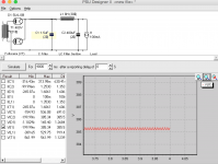
Aha! Yes! I was just able to model it in PSUD as well. Looks like I needed to back out the C filter before adding the RC.
Thanks!
I'll need to order a few small caps and resistors so I can fiddle with the B+.
Has anyone had any experience engineering this run the KT88s a bit hotter? Pete advised that a B+ of 450V with a cathode resistor of 550R might get about 40W out, as opposed to the 26W I would get based on the 370V and 400R resistor that Pete is using.
Kofi
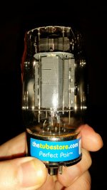
Hey! Parts have arrived!
Everything is here now with the exception of the Edcor transformers (power, choke, OPT), which will hopefully ship next week.
Check out the photos...
Everything is here now with the exception of the Edcor transformers (power, choke, OPT), which will hopefully ship next week.
Check out the photos...
Attachments
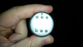
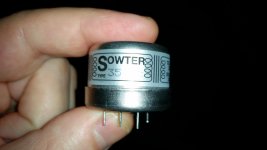
So, if you take a look at the Sowter 3575C transformer, you'll notice that there is a mark next to one of the pins. Based on the pinout on the Sowter website (see below), I'm thinking this mark is identifying pin #2, the connection to the transformer core / case.
Does that seem right?
Does that seem right?
Attachments
Member
Joined 2009
Paid Member
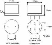
Thanks! I'll check the resistance to be sure. In the meantime, some confirmation from the source:
"The black dot marks Pin 2 which is the screen.
I have attached a new data sheet to indicate this.
Best regards,
Ruth
Mrs Ruth Loveday
E.A.Sowter Ltd.
The Boatyard
Cullingham Road
Ipswich
IP1 2EG
England."
"The black dot marks Pin 2 which is the screen.
I have attached a new data sheet to indicate this.
Best regards,
Ruth
Mrs Ruth Loveday
E.A.Sowter Ltd.
The Boatyard
Cullingham Road
Ipswich
IP1 2EG
England."
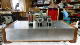
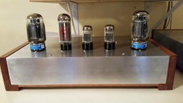
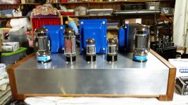
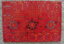
Some progress recently...
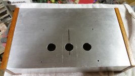
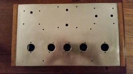
I drilled the top plate for the tubes and fit the circuit board. I'm still waiting for transformers from Edcor (going on eight weeks now) but I've left plenty of room in the back of the chassis.
More updates to come.
Kofi
I drilled the top plate for the tubes and fit the circuit board. I'm still waiting for transformers from Edcor (going on eight weeks now) but I've left plenty of room in the back of the chassis.
More updates to come.
Kofi
Attachments
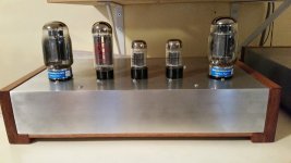
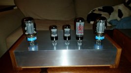
I've finished the first chassis. I tried to polish the aluminum and I thought it came out OK. Photos below...
Kofi
Kofi
Attachments
Warning, OT
This is OT. Kofi, we started on our DIY Audio quests at about the same time. Seeing your name made me remember the great times I had reading your exploits. You should go back and read your first posts. It is astounding how far you have come. I would hazard a guess that you would want a thermistor or a set of antiparallel diodes or some such thing between circuit ground and chassis ground to keep grunge from the chassis ground out of your amp, but do not take my word for it. Perhaps someone who actually knows something will provide an answer to your query. Remember the old barnacle with rubber feet. No reason to, but I do. -Thanks, all the best to you- marsupialx")
This is OT. Kofi, we started on our DIY Audio quests at about the same time. Seeing your name made me remember the great times I had reading your exploits. You should go back and read your first posts. It is astounding how far you have come. I would hazard a guess that you would want a thermistor or a set of antiparallel diodes or some such thing between circuit ground and chassis ground to keep grunge from the chassis ground out of your amp, but do not take my word for it. Perhaps someone who actually knows something will provide an answer to your query. Remember the old barnacle with rubber feet. No reason to, but I do. -Thanks, all the best to you- marsupialx
Last edited:
Seeing your name made me remember the great times I had reading your exploits. You should go back and read your first posts.
Yeah, I went back and read some posts of my first Gainclone build. What a nightmare. I had absolutely no idea what I was doing. I feel lucky to be alive.
Thanks for the kind words.
I would hazard a guess that you would want a thermistor or a set of antiparallel diodes or some such thing between circuit ground and chassis ground to keep grunge from the chassis ground out of your amp
Yeah, I agree about the anti-parallel guys, but I'm wondering if I should choose a a different point on the PCB ground plane to connect to the chassis ground. I'm thinking the negative lead of the first supply cap would be best, but given that it is a ground plane (and not a star ground, per se) it may not matter as much where it is connected.
Thanks again for responding. Always good to hear from a fellow DIYer from back in the day.
Kofi
- Status
- This old topic is closed. If you want to reopen this topic, contact a moderator using the "Report Post" button.
- Home
- Amplifiers
- Tubes / Valves
- Kofi's Uniamp