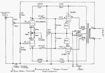
Do I have the balance pot on the ECC803S wired correctly? I have it as:
Pin 3 sees 470R resistor and leg 3 of the pot
Pin 8 sees 470R resistor and leg 1 of the pot
Leg 2 of the pot sees the two ends of the 470R resistors AND the CCS in
Is this right?
Yes thats right. Now there are a few variant schematics of this amp, one shows the 1K and 1K6 positions reversed. Can you post up the main amp schematic you are using so we are all on the same page?
Last edited:
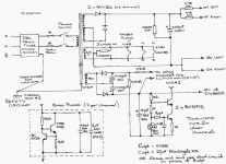
Thanks. Also check that your LED is in the right way around. There is a little flat on the rim of the LED next to the negative (cathode) lead. This should be connected to the -13V power supply, the negative end of the 47uF cap and the lower end of the bottom 1K resistor.
Here's a simple test for the CCS:
http://www.diyaudio.com/forums/tubes-valves/72536-el84-amp-baby-huey-41.html#post1472317
Here's a simple test for the CCS:
http://www.diyaudio.com/forums/tubes-valves/72536-el84-amp-baby-huey-41.html#post1472317
Would a 680R do?
Rather something like 120K from the pot to -13V PSU. I suppose.
OK-- so I ran a 120K between the -13V supply and the balance pot and the ECC803S plates see 300V to ground now, but the supply is still sitting at 380VDC for the B+. Furthermore, the 120 resistor is dropping about -18V, which means that there's only .15mA running through the tail of the ECC803S, which seems too low, correct?
Interestingly, the voltage at the first 10uF cap is 382VDC and it's 380VDC after the choke. I would have expected the choke to drop more volts. Maybe the choke is a dead short?
Mother. Father.
Kofi
Interestingly, the voltage at the first 10uF cap is 382VDC and it's 380VDC after the choke. I would have expected the choke to drop more volts. Maybe the choke is a dead short?
Mother. Father.
Kofi
Says the cathodes of the ECC803 should be at +3V and the current should be 1mA, that means that the resistor simulating the CCS will have 16V accros it, so its value should be (R=U/I) = 16/1 = 16K.
Not so far from the 18K Salas sugests.
Then check that the anodes of the ECC803 are around 100 to 150V.
And check the cathode voltages of the EL84 too.
Looks like if your CCSs (both) don't draw anything . . .
Not so far from the 18K Salas sugests.
Then check that the anodes of the ECC803 are around 100 to 150V.
And check the cathode voltages of the EL84 too.
Looks like if your CCSs (both) don't draw anything . . .
OK-- so I put 16K between the ECC803S balance pot and the -13V supply and got these voltages (all voltages are between pin and ground):
ECC803S cathodes: 2.3V
ECC803S anodes: 212V
Three of the EL84 cathodes are at 21.6V
One of the EL84 cathodes is at 14.6V
Obviously I have a bias block to attend to here, but this shouldn't be causing any other issues other than the bad cathode voltage on one side of an EL84, right? Is the 21.6V correct? Any ideas on why the anode voltage for the ECC803S is so high?
Rrrrrrrrrr.....
Kofi
I don't know specifically for the Huey so to tell you voltages, others will hopefully do, or you can find in its original thread, but the input tubes circuit looks it works pulling current with the resistor test is one thing. Check with the Ameter if the output section tubes pull current too. Break their circuit somewhere to measure, because your main PSU not dropping across the choke is fishy that maybe not your output CCSs work too.
I fear you have three bias blocks dead.
14.6V is the nearest of the target, I bet 10 to 12V be better.
At 21V, the EL84s don't draw enough current, that explains why B+ is so hi and voltage across the choke is so low.
Obviously CCS don't like you . . . and vice et versa !
Insure the resistor in the bias block is 16R but the most probable failure is blowed BJTs.
The anode voltage of the ECC803 is too high because the current thru the tube is too low. Reducing the temporary 16K to -may be 10K- (or repairing the CCS) will cure that.
OK-- so I noticed that I made a mistake in the bias blocks. I incorrectly put the 5K6 resistor between the collector and emitter of the MJE340. I changed the resistor position to be between the base and the collector and now the cathodes of the 803Ss all read 21V to ground.
I know from a previous post that they should be much lower and the overall B+ voltage is still waaaaay too high (about 390V). I completely rebuilt one of the bias blocks and I don't see any change in the 21V voltage to ground.
As I mentioned earlier, the LEDs in the CCS are now lighting up after a full rebuild, so I'm thinking I may need to replace the bias blocks with a resistor to see if that sets the correct current.
Any thoughts?
Kofi
Thought I had a problem with my bias blocks and ECC803s ccs when building my baby huey. Had similar high voltages on ECC803's and El84's on first build. Reasoned that the transformer was not under any load as none of the valves were conducting. Replaced the ltp ccs with a 690 ohm resistor and each EL84 bias block with a 270 ohm cathode resistor in order to rule them out. Worked fine and the sound was so good the resistors were left in for a week. The ltp ccs problem was caused by an unconnected earth wire. The bias blocks worked fine when they were inserted.....
HTH Bill
HTH Bill
- Status
- This old topic is closed. If you want to reopen this topic, contact a moderator using the "Report Post" button.
- Home
- Amplifiers
- Tubes / Valves
- Kofi Annan in: "Kofi's Baby Huey"

