As far as the cathode bypass caps are concerned, I'm thinking you're talking about the 100uF / .22uF combo off the EL84s, correct? If so, I'll gladly give the 39R resistor a try. If I'm wrong about the caps you're talking about, please let me know.
If you are going to try my csthode cap idea, you need MUCH MUCH more than the 100uF you can get away with in a conventional setup.
My PP-1C uses 8000uF cathode caps - way overkill maybe, but it improved the bass tonality greatly. But they need to be good caps, switchmode caps are the best.
Regards, Allen
Kofi,
No I'm not talking about that 100uF + 0.22uF cap. I'm talking about the 470uF + 1uF caps shown on "bias blocks" on sheet 2 of the schematics, that is the Current Source bypass capacitors. On my build these capacitors are now actually 1000uF Blackgate + 1uF Polypheylene Sulphide (PPS). I think I might have talked about PPS caps before - this was the dielectric introduced to replace polycarbonate, they have great sound or to be more correct they do not interfere with the sound, ONLY available up to 400 Volt rating which is a bit of a shame.
The Blackgates are now difficult to find. If I had to rebuild this tomorrow using "garden variety" readily available capacitors, I think I would try 5 off Nichicon 220uF 50V ZL Series in parallel in place of the 1000uF Blackgates. I had good results from these ZL Series caps in several (boo hiss) Solid State Amps I built. Don't be tempted by the smaller Nichicon ZLH Series caps, in the SS Amps, these had an aggessive edge I really did'nt like. Some Panasonic (FC Series IIRC) electrolytics are also good.
Cheers,
Ian
Last edited:
jkeny,
The "Ring of two" current sources are more than adequate for the EL84 cathodes. You are working in a low impedance part of the circuit (looking into the EL84 cathodes you see an effective impedance of 1/gm or about 100 Ohms) so a CCS with an impedance of megohms will be a waste of time. Anything with an impedance of say 100 x 100 Ohms = 10K or better will be fine. The "ring of 2" is at least 10 times better than that minimum specification.
Cheers,
Ian
Yep,
remember that the primary characteristic of a current source is a very high impedance to AC signals - so the audio signal path is via the bypass caps. The CCS's are designed to balance the push pull idle currents very closely which improves the fine detail and bottom end. My post above is not quite right - with an unbypassed CCS in each of the push pull cathodes you would get nothing - you could get Class A only operation by connecting the 2 cathodes together and using a single CCS (this is the Allen Wright DPA300 scheme) or by using separate CCS (like the Baby Huey) and tying the cathodes together at AC by using a big non polarised capacitor or back to back electrolytics from cathode to cathode (Sheldon has used this scheme).
Since the AC path is via the bypass capacitors you can see what that suggested 39 Ohms is doing. It is in the common AC path and so is generating some common mode feedback for the output tubes.
Cheers,
Ian
Last edited:
Kofi,
No I'm not talking about that 100uF + 0.22uF cap. I'm talking about the 470uF + 1uF caps shown on "bias blocks" on sheet 2 of the schematics, that is the Current Source bypass capacitors. On my build these capacitors are now actually 1000uF Blackgate + 1uF Polypheylene Sulphide (PPS). I think I might have talked about PPS caps before - this was the dielectric introduced to replace polycarbonate, they have great sound or to be more correct they do not interfere with the sound, ONLY available up to 400 Volt rating which is a bit of a shame.
The Blackgates are now difficult to find. If I had to rebuild this tomorrow using "garden variety" readily available capacitors, I think I would try 5 off Nichicon 220uF 50V ZL Series in parallel in place of the 1000uF Blackgates. I had good results from these ZL Series caps in several (boo hiss) Solid State Amps I built. Don't be tempted by the smaller Nichicon ZLH Series caps, in the SS Amps, these had an aggessive edge I really did'nt like. Some Panasonic (FC Series IIRC) electrolytics are also good.
Cheers,
Ian
Got it! Thanks!
Do you mean Rubycon ZL? I don't find the ZL series in the Nichicon, but I do find them in the Rubycon: http://www.newark.com/jsp/search/productdetail.jsp?SKU=31M6650&CMP=AFC-GB100000001.
Kofi
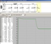
Here's the current PSU. Note that there are no resistors, per Sheldon's comment. This should give around 312VDC, but is the ripple acceptable?
Also, if I went with an oil cap for the last one I could only get about 40uF, which would increase ripple but would allow a non-electrolytic as the end cap. Which is more desirable?
If the ripple is acceptable, you are getting good CMRR, which means that the last cap is not really in the signal current loop, so even though a film cap is large enough, an electrolytic is fine.
If, on the other hand, the ripple is not acceptable, then it means that the cap is in the signal current loop, so you would want a film cap, but you would also want a better PS to reduce the ripple meaning that you might need the electrolytic anyway.
Were it me, I'd try a big electrolytic here, and if there is too much ripple, put in a simple regulator followed by a small film cap.
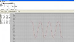
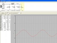
My modelled psu for the Baby Huey.
I1 and I2 show 20mA because thats how PSUD works. I've started each channel on 20mA and it goes up to 80mA after 2 seconds. (I'd rather PSUD shows the 2nd value of the current tap.
Thing to look for is lack of ringing. Which seems to be the case.
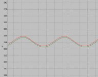
Closeup:
Attachments
Last edited:
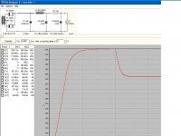
If you mean you are splitting the supply after the choke, then that's not the way to model it. You show them in series, but they should be modeled in parallel. Use one RC and one current source. Double the capacitance, halve the resistance and double the current.
Sheldon
Like this?
Current doubles from 40ma to 160ma after 2 seconds
Note: changing the R value from 1 ohm to 100 ohms gets back to around 335V B+ with less ripple in this model.
Attachments
Last edited:
Yes you are correct of course. I knew that. But just wanted to demonstrate clearly the branching after the choke.If you mean you are splitting the supply after the choke, then that's not the way to model it.
")
- Status
- This old topic is closed. If you want to reopen this topic, contact a moderator using the "Report Post" button.
- Home
- Amplifiers
- Tubes / Valves
- Kofi Annan in: "Kofi's Baby Huey"