I have an inverse RIAA circuit that I used to check my pre with. Happy to send it to you if you want to contact me offline.
Contacted! Thanks!
Thanks to your posts I built the TL "El Cheaop" phono and linestage. It sounded very good (indeed the best of the handful of phono stages I built) but I have a problem with excessive hum. I'm rebuilding it in a larger case, paying attention to layout and wiring sheme.
Hey-- let's get this clear. My posts are always the questions, not the answers. It's really Thorsten you should be asking. But thanks... it's good to know my ignorance is beneficial to at least one person.
I too had a hum problem with the El Cheapo initially, until I built an offboard supply and grounded according to Thorsten's instructions.
Did you do the "dirty diode" trick? Note that in my diagram in the grounding posts, my bridge diode needed to be turned 45 degrees to work properly.
Kofi
Thanks Salas and Kofi.
My PSU is an off-board 4-stage CRC (not regulated). The hum was quite strong, though strangely on one channel only (at least mostly). But I was using braided single-core wire, with the braid connected to circuit ground, as my input / output connection. A member on this forum told me that it acts like an antenna!
Kofi, I wasn't expecting answers from you (sorry) but yes I wanted you to know
I did the "dirty diode" trick - in fact I used your diagram - and noted the change in the bridge diode connection. It will be a few days till I continue the project with new wiring/ layout/ test.
Thanks and regards,
Joe A
My PSU is an off-board 4-stage CRC (not regulated). The hum was quite strong, though strangely on one channel only (at least mostly). But I was using braided single-core wire, with the braid connected to circuit ground, as my input / output connection. A member on this forum told me that it acts like an antenna!
Kofi, I wasn't expecting answers from you (sorry) but yes I wanted you to know
... it's good to know my ignorance is beneficial to at least one person.
I did the "dirty diode" trick - in fact I used your diagram - and noted the change in the bridge diode connection. It will be a few days till I continue the project with new wiring/ layout/ test.
Thanks and regards,
Joe A
I highly recommend you a regulated psu, a Maida or better a shunt.
Also use well shielded coaxial wire for inputs and outputs. It takes several experiments with grounding, layout & wiring, until you start to 'visualize' correct current paths and avoiding hum fields. See, you can do better for hum and noise than even some very good commercial machines in the end. The black line on the photo is one of my NJFET simplistic RIAA builds + my low voltage shunt, having a toroidal transformer very near to it in the same small box. It can be made even better, no special precautions taken, to the contrary a bit challenged. Just good basic practices in the DIY one shown. The blue line is a 10k$ high end American phono stage with double mono psus.
Also use well shielded coaxial wire for inputs and outputs. It takes several experiments with grounding, layout & wiring, until you start to 'visualize' correct current paths and avoiding hum fields. See, you can do better for hum and noise than even some very good commercial machines in the end. The black line on the photo is one of my NJFET simplistic RIAA builds + my low voltage shunt, having a toroidal transformer very near to it in the same small box. It can be made even better, no special precautions taken, to the contrary a bit challenged. Just good basic practices in the DIY one shown. The blue line is a 10k$ high end American phono stage with double mono psus.
Attachments
Yes, yes, mr. Kofi Annan.
But, if without insults...))
At Steve there will be some problem with a sound. Proceeding from my experience of designing RIAA-preamp.
Regimes of tubes too thin.
No optimum for a sound impedance RIAA - chains is chosen. Very high. It is more reasonable to apply to such high impedance in the capacity of the first tube a sounding pentode, for example Telefunken EF14.
BW, VU
Vlauga said:t Steve there will be some problem with a sound. Proceeding from my experience of designing RIAA-preamp.
Regimes of tubes too thin.
No optimum for a sound impedance RIAA - chains is chosen. Very high. It is more reasonable to apply to such high impedance in the capacity of the first tube a sounding pentode, for example Telefunken EF14.
BW, VU
The Bench amp first section is a cascode. Electrically, and sonically, it's very much like a pentode.
It takes special ears to hear an amp from the schematic.
Sheldon
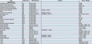
Attached is a screen grab of my working parts list for the audio circuit. I'll follow this up with PSU details and some layout drawings as I complete them.
Any glaring problems with this list? Note that I could not get a 51.1K resistor for the cartridge load in a Vishay or Caddock (which I understand are the ones to go with here), so I'm using a straight 51K for this position. I don't know that the additional 100R will make a difference, but I thought I'd point this out for comment.
Kofi
Attachments
What Salas said. Note that the load resistor has no effect on the performance of the phono amp itself. It loads the cartridge. Some cartridges may like a little more, some a little less. The usual load resistor is 47k. Anything around that value is fine for starters. A little higher value makes it easier to adjust the value. You can leave the original load resistor in place and parallel in a resistor to lower the combined value. Some cartridges like a little added parallel capacitance too. But you have to take account of the capacitance of your interconnects, especially if they are longer.
Sheldon
Sheldon
Indeed. Surely for MM. There are some other scenarios worthy of mentioning too. Maybe someone uses a high output MC that may load better down to a few kOhm. So it can be substituted for 1k-10k by ear. If there is an MC and a step up transformer involved, that load resistor will reflect to the primary divided by the squared step up ratio. I.e. If a 10X ratio is used then 47K/100=470R. It can still be chosen differently than 47k so to manipulate that impedance reflection given the individual cartridge electrical damping needs.
And further: When you do your layout leave some room to place the parallel resistor or caps. Make it easy to get to so that you can adjust and listen. You might consider a place on the rear panel. Also, you can get small pin sockets that don't require a solder joint to the added resistor and/or capacitor. I'm using Lundahl step up transformers, and you can get them with a little board that has a pair of such pin sockets. Here's an example of the sockets: http://search.digikey.com/scripts/DkSearch/dksus.dll?Detail&name=ED5009-ND
Leave room too for a MC step up, if you think you might want to go that way in the future. They're small, but very sensitive to magnetic fields, so keep that in mind when planning placement.
Sheldon
Leave room too for a MC step up, if you think you might want to go that way in the future. They're small, but very sensitive to magnetic fields, so keep that in mind when planning placement.
Sheldon
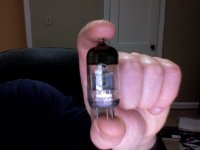
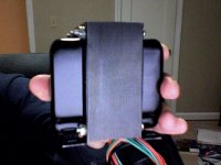
Transformers finally arrived from Jack yesterday and they're real mothers (photos to follow).
Sheldon-- great advice on the pin sockets! I'm also using Lundahl step up transformers for my MC (Dynavector 20X-L).
Placing orders for all remaining parts this weekend. More to come...
Kofi
Sheldon-- great advice on the pin sockets! I'm also using Lundahl step up transformers for my MC (Dynavector 20X-L).
Placing orders for all remaining parts this weekend. More to come...
Kofi
Question on Series-Parallel Heater Connection
Prodded by the excellent feedback on this thread, I have finished wiring Steve Bench's phono preamp. In my scheme of things the heaters are wired in parallel for 6.3V. That means pins (4+5) and 9 of the 12ay7s are one set and pins 4 and 5 of the 2 ecc88 are another set. The idea is to feed each set with a separate 6.3V CCS using the 317 circuit described earlier by Salas.
My question is: For testing purposes can I use a 12V transformer to supply a common CCS to the two parallel sets in series, as I try to show below?
o----------12.3V ccs--------o
| |
-----VVV-----o------VVV-----
| || |
| ecc88 || 12ay7 |
| || |
-----VVV-----o------VVV-----
As the 2 valve types draw different heater current, will each valve see the correct voltage/current it needs? If the answer is yes to both questions, is it correct to correct to calculate the ccs resistor by dividing 1.25V by 0.665A which is the total of one 12ay7 (300mA) and one ecc88 (365mA) which brings it to 1.9R approx?
Thanks for your help.
Joe A
Hi,
Don't feed different heater current valves in series from the same CCS. They will pass the current dictated by the CCS and will develop a voltage across that will be right only for one type. Just because they are near in this instance, you may try 330mA and see if they will fall in their +/- 10% tolerance. But its not really right.
Don't feed different heater current valves in series from the same CCS. They will pass the current dictated by the CCS and will develop a voltage across that will be right only for one type. Just because they are near in this instance, you may try 330mA and see if they will fall in their +/- 10% tolerance. But its not really right.
Re: Question on Series-Parallel Heater Connection
You can use a common transformer to supply some CCSs. See what will happen when trying to run a mid in between demands current through 12AY7 & ECC88, with their heaters configured in parallel for each one. 6922 has 300mA nominal though...
sonata149 said:My question is: For testing purposes can I use a 12V transformer to supply a common CCS
Thanks for your help.
Joe A
You can use a common transformer to supply some CCSs. See what will happen when trying to run a mid in between demands current through 12AY7 & ECC88, with their heaters configured in parallel for each one. 6922 has 300mA nominal though...
Attachments
Hi Salas,
Thanks for your replies. However,
I'm not sure I understand you correctly. Assuming the 2 sets of valves are wired for 6.3V operation, in parallel, each set will be powered from a common PS from which two CCS are issued. I suppose the current has to be doubled (parallel connection). Isn't that so? So, one CCS 'tree' has to deliver 600mA, the other 730mA.
Excuse my newbie questions. Thanks.
JA
Thanks for your replies. However,
On the other hand, why not two CCSs, one 300mA, another 365mA, and two trees, one 12AY7 tree, one ECC88 tree?
I'm not sure I understand you correctly. Assuming the 2 sets of valves are wired for 6.3V operation, in parallel, each set will be powered from a common PS from which two CCS are issued. I suppose the current has to be doubled (parallel connection). Isn't that so? So, one CCS 'tree' has to deliver 600mA, the other 730mA.
Excuse my newbie questions. Thanks.
JA
- Status
- This old topic is closed. If you want to reopen this topic, contact a moderator using the "Report Post" button.
- Home
- Amplifiers
- Tubes / Valves
- Kofi Annan in: "Cascodin' with Steve Bench's RIAA!"