Redshift187 said:
Ummm, no. There aren't any that cost that much, and he doesn't use the most expensive ones. I believe he uses 2x 100 uF and 2x 1000 uF per channel. That's $12 x 2 + $14.50 x 2 per channel, or $53 per channel (assuming dual mono). Way too much for caps by my standards (because the rest of my amp isn't up to that quality), but that's an individual opinion.
oh I thought they were the 50v 1000uf NX's that are in the pic on his site
dammit why can't you edit posts for more than a half hour on here

anyway, I'm also thinking about building of Papa's B1 buffered preamps on perfboard to put in the same case with my GC. Is there a simple way to power it from the GC PS? For those that don't know, the B1 needs 18-24VDC and uses 20mA or less
I didn't mean using a separate GC PS board to power it, I meant powering it off of one I'll also be using for the amp. So the problem is that I plan on using a toroid with 22V secondaries, which becomes about 31VDC when rectified, correct? So what I meant was is there an easy way to turn 20mA of the power from the GC PS to 18-24V. That would be a drop of 7-13 volts. Maybe a simple LM317 circuit on a small piece of perfboard? Or just on the same piece of perfboard I put the B1 on? What would such a circuit look like, other than the regulator and the resistor to set the voltage?
Hmm, realistically it's looking like the B1 will have to wait till later if I'm gonna stay within my budget (which I need to), but we can still plan it right?
Hmm, realistically it's looking like the B1 will have to wait till later if I'm gonna stay within my budget (which I need to), but we can still plan it right?
Yes, adding regulators to power the buffer off unregulated supply from the amp would work, in fact I tried such approach once, you can see pics here: http://www.diyaudio.com/forums/showthread.php?s=&threadid=39582
pinkfloyd4ever said:HOLY SH!T for $60 apiece!?!?I think I'll pass on those
Those would be BG N 1000/50 caps, I was using them for a while, but later switched to different grade and it worked better. You can read all about it here:
http://www.diyaudio.com/forums/showthread.php?postid=574431#post574431
http://www.diyaudio.com/forums/showthread.php?postid=581230#post581230
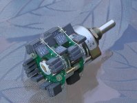
pinkfloyd4ever said:I'm still debating on volume controls... linear Panasonic EVJ with shunt resistor (cheapest of course), SKA Optivol, or a Nobel 31-pos stepped attenuator
If you are looking for a best volume control, for my kit, it would be fixed series, switched shunt type, based on Elma switch, 10k Vishay S102 and Caddocks MK132 in most frequently used positions (the other can be Dales to save on cost). Why it's the most suitable, because nothing is added to the amp's circuit, you just replace one series resistor with another (R1 220R Caddock with 10K Vishay, and in place of R2 22k Caddock a selectable Caddocks are inserted), in other words it's exatly same or better parts, that allow you volume adjustement. I tried it and it works great.
Attachments
Peter Daniel said:Yes, adding regulators to power the buffer off unregulated supply from the amp would work, in fact I tried such approach once, you can see pics here:...
Awesome, thanks..VERY helpful as usualPeter Daniel said:Those would be BG N 1000/50 caps, I was using them for a while, but later switched to different grade and it worked better. You can read all about it here: ....

umm I'm not gonna lie, I have no idea what that means..could you explain what a fixed seried switched shunt stepper is? Or direct me to somewhere that gives a good explanation? I'm interested to learn, although I know a stepper made out of Caddocks is gonna be WAYYYY out of my budget, since I'm trying to keep everything under $200. I was just considering a Noble stepper cause somebody in the DIY forums at head-fi had bought one off ebay for about $30 shipped but of course those have sold outPeter Daniel said:If you are looking for a best volume control, for my kit, it would be fixed series, switched shunt type, based on Elma switch, 10k Vishay S102 and Caddocks MK132 in most frequently used positions (the other can be Dales to save on cost). Why it's the most suitable, because nothing is added to the amp's circuit, you just replace one series resistor with another (R1 220R Caddock with 10K Vishay, and in place of R2 22k Caddock a selectable Caddocks are inserted), in other words it's exatly same or better parts, that allow you volume adjustement. I tried it and it works great.
 I did get a 50k Hafler pot though...didn't know much about it honestly, anyone know if it'll be any good?
Okay for 8 Ohm speakers. With 4 Ohm the amp might reach its thermal limits.pinkfloyd4ever said:would this 230VA dual 24V secondary transformer work well for a gainclone?
That is exactly the difference from dual mono to stereo. Dual mono uses two transformers, stereo uses one.pinkfloyd4ever said:Is it a bad idea to use one dual secondary transformer for a dual mono setup?
Not possible. You have to feed both amps in parallel off both secondaries.pinkfloyd4ever said:(using one secondary per channel of course)
pinkfloyd4ever said:(using one secondary per channel of course)
The amp uses symmetrical PS (+/-V) in each channel. To get this, dual secondaries are needed (per each channel). With single transformer, there is no other choice but to use them in parallel.
See schematic for details: http://www.diyaudio.com/forums/attachment.php?s=&postid=1508798&stamp=1210694958
That will work. Thanks Peter. Oh I got the kit and I must say it looks great. Cant wait to get the boards built. I just received my final aluminum bar order last night. I also got a 2" X 1/4" X 48" bar of copper to cut into pieces to use as heat sink. Should look nice polished up.
worddanielwritesbac said:In my opinion. . .
For either, a buffer or impedance match device of some sort, or preamp, are generally reported to give a more euphonic sound.
pinkfloyd4ever said:
anyway, I'm also thinking about building of Papa's B1 buffered preamps on perfboard to put in the same case with my GC. Is there a simple way to power it from the GC PS? For those that don't know, the B1 needs 18-24VDC and uses 20mA or less ...... So the problem is that I plan on using a toroid with 22V secondaries, which becomes about 31VDC when rectified, correct? So I meant is there an easy way to turn 20mA of the power from the GC PS to 18-24V. That would be a drop of 7-13 volts. Maybe a simple LM317 circuit on a small piece of perfboard? Or just on the same piece of perfboard I put the B1 on? What would such a circuit look like, other than the regulator and the resistor to set the voltage?
I prob won't have the cash to do it all up front, but I plan on eventually (hopefully by the end of the year) using a B1 with an OptiVol, which I think should make this one hell of a budget speaker amp
Peter Daniel said:
The amp uses symmetrical PS (+/-V) in each channel. To get this, dual secondaries are needed (per each channel). With single transformer, there is no other choice but to use them in parallel.
See schematic for details: http://www.diyaudio.com/forums/attachment.php?s=&postid=1508798&stamp=1210694958
Are there any major disadvantages to using them in parallel compared to seperate dual sec trannys per channel. Im assuming by the pcb layout (multiple holes for each of the PG and V) , and the fact that you only sell dual mono kits, that you simply use one of the retifier boards when going for a stereo setup...Please correct me as i am new around here lol

opps i found this just then:
Q. What kind of improvement do we get by adding an extra power supply?
A. By adding another power supply, you make it into a complete mono structure. It also adds more power (does not double though) and current capacity. The result is an airier, deeper soundstage and more authotity through the entire frequency range.
Guess that kinda answers the question. But i feel that i havent seen many dual mono, single chassis models around...
I've emailed Brian at chipamp.com several questions and have yet to get a reply.
I wanted to know if he would sell me a kit with ONLY the parts for the amplifier and leave out the power supply PC and parts (I have lots of surplus rectifiers and capacitors that won't fit his PC board, and prefer to wire the PS point to point anyway). Based on his prices for the other kit combos it seems like his price on the amps alone should be $20 for mono / $40 stereo, etc.
Question for Peter: could I buy his amplifier PC boards by themselves without the PS boards, and what pricing?
Finally LM3886 vs LM3875 vs LM3876. It seems that the LM3876 is the same as the LM3875 except it adds the mute function, and the LM3886 adds an additional power pin connection. Can the boards from either Audio Sector or Chip Amps be adapted to use the 'other' kind of chips? I thought NS had discontinued the LM3875 and 'replaced' it with the LM3876. These two chips are identical except for the mute function, while the LM3886 has different parameters. You can sometimes get the LM3875/6 chips slightly cheaper than the LM3886, but the LM3886 is slightly easier to find. The difference in power between them is too small to hear and I've read conflicting reports of which sounds 'better'.
On your product question. . .
The Audiosector product has really good support. The LM3875TF is the new insulated version that replaced the older LM3875T.
Audiosector has the gainclone. That is a low component count amplifier. As such, it can magnify/illustrate component differences (because there are so few components). Therefore, in order to know what it should sound like, you'd need to build it exactly on spec, with the recommended model numbers for every component except. . . well, there is no exception. The support thread is a "sticky" at the top of the chipamp forum.
Audiosector build thread: http://www.diyaudio.com/forums/showthread.php?s=&threadid=123003&perpage=50&pagenumber=1
The Chipamp.com product is a power amplifier starter kit. The layout is somewhat more like a traditional amplifier. Although the power supply is an abbreviated version "inspired by" the CarlosFM supply, you may want to add the rest of the components (just use the search feature). Single LM3886's are able to tolerate 4 ohm speakers, and this little kit is quite powerful.
As for the sound of either, I'll just say that they're quite clear. If you have tonality preferences that aren't provided by your speakers, this issue will increase dramatically. A Creative Labs X-FI Gamer (previously named Xtreme Music) does happen to have a lossless EQ although the many other effects aren't lossless (the thing is worth it for the EQ).
Another lossless EQ method is a 3-way speaker with L-Pads to adjust for ear and room. In fact 3-way speakers can be constructed with efficiency of about 95db, which is in range to use the rather beautiful LM1875.
Audiosector has the Parallel option for the 4780, and Parallel operation decreases the "distortion rises with frequency" issue of the LM3886's (of which there are two inside the stereo chip). Some do report that the 4780 Parallel has a nicer tonality and/or less variance between usage on different types of speakers. The parallel amp is a good choice for giving a mighty shove to troublesome speakers, like the compact 4 ohm mtm's that are currently popular.
At Decibel Dungeon, you'll find some nifty point-to-point methods for using either LM3875 or LM3886. There are also some preamp projects.
DC offset may be an issue for some of the projects. Its not documented well at all. National Semiconductor sometimes illustrates a 20k pot with a 20k resistor as the input load. There's a clue. That's a combined total of 10k and won't make DC offset. However, there could be DC offset if a cap is placed between the pot and input load resistor or if the pot is removed. Use cap-pot-resistor layout or use a 10k to 15k input load resistor if you get DC offset.
Also not well documented is. . . if you don't happen to like the sonics of your LM3886 or LM3875 power amp, just decrease the gain. That decreases its contribution by the same factor. Next, just give it a push with a lovely sounding preamp.
Further information: http://myweb.tiscali.co.uk/nuukspot/decdun/gaincloneindex.html
As to dc offset....
Using Ci in the feedback path (between the inverting input resistor and ground) will eliminate the DC offset problem by reducing the gain of the amplifier to zero for DC. The recommended value for Ci varies greatly with common values between 22uf to 100uf, although I've seen lower values used (around 4uf non electrolytic types). Non polarized electrolytic types are sometimes recommended here but often conventional electrolytics are used. The polarity of such caps is often shown in either position (plus to ground, or plus to the inverting input). This isn't a surprise since the dc voltage across the cap is probably almost zero anyway, so the voltage rating of the cap isn't a factor either. When high value caps are used here (to get the LF cutoff below 20hz with little phase shift) the cap is often bypassed with a smaller one (.1 uf).
using a coupling capacitor between the source and the input also will eliminate the DC offset problem provided that the inverting input is returned to ground for DC (as opposed to being left floating). The value for this capacitor is usually much smaller than that used for Ci. I've seen 1uf to 2.2uf in most cases, but I made use of some 4uf polyprop caps salvaged from some speaker crossovers. They don't fit on the board, but that's no problem since they go between the amp input and the wiper on the volume pot.
As usual, these things probably sound better with fewer caps in the signal path. There are other ways to handle DC offset such as with an error servo but they have their own issues.
- Status
- This old topic is closed. If you want to reopen this topic, contact a moderator using the "Report Post" button.
- Home
- Amplifiers
- Chip Amps
- kit differences: chipamp.com vs audiosector.com