Interesting idea, I'd suspect that the original 12B4 were probably not that closely matched in the first place and that one could probably find good used ones that were close enough. (Or maybe new ones)
I'd be hesitant to recommend making any irreversible modifications since this system is a bit of audio history. I might consider changing to the Futterman implementation if not too many other changes were required.
I'd be hesitant to recommend making any irreversible modifications since this system is a bit of audio history. I might consider changing to the Futterman implementation if not too many other changes were required.
On second thought, putting triodes in one tube bank and a big pentode in the other would produce an asymmetric output impedance. Although that might just mimic the 2nd harmonic effect of the original mis-matched bank gains. There are amplifiers around that use a V source versus an I source for P-P. Nelson Pass for example. The current output gains would need to be matched for sure.
Alternatively, some local shunt "Schade" like N Fdbk could be added to the pentode group to match the triode group Zout. The bank driver would need modification then (current sourcing). Build the add on pentode(s) and driver mod on a separate bolt-on sub-chassis. (no need for any obvious mods to the original equipment part.)
In any case, some tube testing and data recording is in order to see what IS available.
Another approach would be to divide up the tube banks (electrically) into sub-sections. Each sub-section with a separate bias control. (possibly a gain control too) Then any assortment of tubes could be partitioned up into roughly matched groups. (and add some quiet fans)
Last edited:
Here are some shots of the Bozak Speakers. The are wired to present a 32ohm load.
Each cabinet contains:
(4) 12" woofers
(2) 6.5" mids
(8) 2.25" tweeters
(1) Jensen 302 super-tweeter
(2) crossover networks
What is the sensitivity of such speakers?
Could they be driven by a "normal" SET amp just to test how they sound?
that is alright Don.....it is really the journey more than the final destination where the thrill is at...the journey is where we pick up lots of gems along the way...
This certainly applies to the acquisition of this group of "gems".
My journey began in 2015 with a casual Craigslist search for "Bozak". I was half-heartily thinking it might be interesting to own a pair. I soon found this pair of outside of Detroit, but it was being sold along with this strange console. After a few weeks of negotiations, I committed to purchased the Bozak speakers and the console. This required renting a van and taking a 770 mile road trip. The seller told me he had done some carpentry work for an elderly lady in Grosse Pointe, MI and had taken the audio gear as partial payment. The woman told him that she had the system installed in their home as a birthday gift for her husband.
The speakers turned out to be massive! They are in pretty good shape but do need some work. Fortunately, there is quite an active Bozak following with plenty of advice on these vintage beasts.
The matching console, it turns out, was the real pleasant surprise in this sale. It is a rolling cabinet, a little smaller than one of the speakers and constructed of the same wood. On the front there is a removable access panel that conceals the pair of preamps, each with their own power supplies. These amps are built with all high quality components. The tubes are (3)7025s and (1)5879. Each power supply uses a 6X5GT rectifier for the main power and a selenium rectifier for the DC filament supply.
Lifting the hinged top will reveal a Fisher FM 100-B tuner. Sadly, someone (MP) modified this unit by removing the original faceplate and fitting it into a custom panel that also accommodated other controls. I think the MP panel is quite ugly. It's hard to improve the classic look of a vintage Fisher faceplate.
To the right of the tuner is a turntable that is obliviously not from the same era. It is a Dual 701 that has been professionally fitted into the console. (Not a bad TT by most peoples standards). Interestingly, I found the name"H.C. Fruehauf" hand engraved into the bed of the TT.
The 701 needs a complete overhaul as it is way out of adjustment and it blows the internal fuse when powered on. It dose have a very nice Sure V-15 III cartridge.
I believe there was originally a tape deck installed where this Dual now resides. In the lower right corner of the console, there is a pull-out drawer where the original turntable was installed. I can't imagine this was very practical or convenient and can understand why one would want to move it the top of the console.
One nice little amenity that was cutting-edge for technology in its day is the handheld remote control. This unit plugs into each preamp and allows the listener to control volume, bass and treble from about 10 feet away from the console.
There were no power amplifiers.
I paid about $800 for all this treasure and then for another $40, the guy sold me a small tube tester and a box full NOS replacement tubes.
Now, a road trip that harvested all of these gems would definitely be considered a success and would normally give the collector years of enjoyment. For me, however, the adventure was just beginning.
The nameplate in the console was an absolute mystery. Not knowing about it left me with a huge void. So, of course, I Googled it. This turned up little more that a obituary for the founder of the company. The lack of information drove me to search deeper. For months I looked and eventually found a clue here and a connection there. Somewhere during this search, I learned about the power amplifiers that would have been paired with this installation. I was even able to locate the schematics for the OTLs. I thought "wouldn't it be great to find a pair of those amps to match back up with this system?"
I continued to search the internet, used advanced search features, posted inquiries in several forums, followed up on leads, sent emails, wrote letters and made phone calls.
In February of 2016, I made contact with a gentleman on the east cost that had family ties to the founder of the company. The man was so impressed with my searching efforts that he volunteered to he introduced to me to another fellow that was very involved with the company when it existed.
When I spoke to him on the phone, it was obvious he was not only very familiar with system that I had, he was also well versed in the entire history of MP Engineering and he certainly qualified as an expert in the audio electronics. I told him that I was interested in learning anything I can about this mystery man Myrko Paneyko and that my ultimate goal was to locate a pair of the OTL power amps to pair up with the system I had. I just about hit the floor when he replied with "I might be able to help you out with that".
We talked several times over the next several weeks and it turns out he not only has a pair of these amps, he has an extra pair and, he is at a point in life where downsizing is a good thing. So, at the end of May, 2016 I rented another vehicle and took another road trip - this time a little over 2000 miles.
I returned home with a pair of OTL amps, a boatload of information and lifetime of memories.
This adventure continues....
What is the sensitivity of such speakers?
Could they be driven by a "normal" SET amp just to test how they sound?
These do not have spec sheets to report that data, but I can tell you they absolutely can be driven by a SET amp. I have a built a Darling amp the pumps out a whopping 3/4 Watt and, with the volume knob at 12:00 it is plenty loud.
I also figured out that I can make a super-simple mod in the speakers to convert them to 8 ohms. I think I'll install a couple of jumper points in the back so I can run them either way.
Thanks,
Joe Y
I agree. I have been tempted to drill ventilation holes into the deck between the tubes to allow air to raise. But, modifying these amps is to that degree is something I am not going to. I would just add a low RPM fan if the heat is a problem.One needs a "chimney" effect to improve air circulation with more heat. The MP amp has got the tubes on a flat plane, their density impairing easy air flow.
The original tubes were all "Raytheon Registered". I assume these were a HQ or Mil Spec version of their standard tube. Mirko had many connections and bought "factory direct" whenever possible. I have not been able to fine any of the "Registered" tubes for replacement, but I have purchased many random brands and have used them in the amps.It's not just socket wiring. Where are the bias adjustments for all those tubes? I only see one for the whole bank. So matched tubes are required there. I would be a really "pi__ed" customer if I had to order 60 matched tubes every time a few went out. It does look like all those tubes were ordered as a single batch from Raytheon. All it takes is one of those tubes to short out, and good-bye speaker.
It turns out "matched tubes" are not necessary. All that is needed is a balanced set of tubes. In other words, I need just as many strong tubes and week tubes on each side of the amp. With all 30 tubes installed, I set the bias voltage to -20 then press the test button. If I can't get the needle to remain in the center "0" position, I'll shut down, then randomly pull a few tubes from the top side and swap them with some from the bottom side. Then power up, set the bias and check the balance. I'll repeat this as much as needed. After a bit, it gets a lot less random. I can even mark some tubes as a + or a - unit. This is not very scientific, but it works.
Of course, I have a dummy load attached, not the speakers.
One thing you might be able to help me out with is this:
Rather than starting out with a full complement of 30 tubes, I'd like to be able to populate the amp two tubes at a time - install one upper and one lower, set the bias, adjust the balance. Then repeat, adding another pair each time. Sort of an in-amp tube matching operation.
My question is: If I utilize an adjustable dummy load, what Z value do I start out with and how much would it decrease with the addition of each set of tubes?
That's funny!If there really was some "military" aspect to this guys work, I would guess the CIA were planning to send this thing to "der Fuhrer", so he would be totally occupied with maintaining his sound system.
OK, anti high tube # OTL rant off. Some significant amount of TLC can likely bring back some nice sound. A few fixes might make good sense.
Rant away.
I get enough high praise and hi-fives on these to wash out any negativity any one man could generate.
Seriously, I don't mind.
Thanks,
Joe Y
Not sure where the OP mentioned that he was short of 12B4’s, anyway, given the rarity of the amplifier, I’d think it would best to restored it to its original condition without any modification...
One of the photos I posted showed the amps as I received them. They had been in storage for at least 30 years and survived two moves. a few of the tubes were missing or broken.
The good news: I also received a 3rd amp along with the pair shown in the photos. Between the 3 amps I more than enough tubes to populate two amps. I also have been buying replacement tubes when I come across them.
Thanks,
Joe Y
...Rather than starting out with a full complement of 30 tubes, I'd like to be able to populate the amp two tubes at a time - ....dummy load, what Z value do I start out with and how much would it decrease with the addition of each set of tubes?...
30 tubes is 15 pairs.
The amp was sold for 32 Ohms.
So a one-pair version would be 480 Ohms.
I don't see much point in exact dummy-loading. It may run fine un-loaded. And that is how we would trim offset in a transistor amp. To be safe, I would run a 470r 10W dummy for one pair, two 470r 10W dummies for two pair, etc... a ten-pack of 10W resistors is not much money, and all-ten or 47r is close-enough for the 15-pair check. Offset will be a bit higher on 47r than with 32r, but you just want "lowest", not an exact number. (4V offset will do no harm for that speaker array.)
@Kasanay, you mentioned that the Dual 701 in the console is not working. I can highly recommend the Dual Doctor in St. Thomas Ontario Canada for a re-build. He did my Dual 1219 last year, and while it's not in the league of my Roksan Xerxes/Artimez/Shelter, it's surprisingly not nearly as far off as I thought it would be. It works perfectly and the Dual Doc was a pleasure to deal with. The cost for a typical re-build is $195 CDN. plus parts. It ended up costing me $350.00 for the 1219 resto including return shipping. Worth every penny. Just FYI
Haven't visited recently, so figured I'd catch up. As OTLs are one of my interests, I could not resist. Fascinating!
Those amps are an important piece of audio engineering history and as already noted should not be modified - just replacing non-functioning parts. I don't know what I would pay for a pair of those, but it would probably be too much as I would hardly be able to conceal my desire to have them.
I read the Music for Millionaires article. We doubtless would know more about Mirko Paneyko and his products had he been willing to advertise, but it seems he was a man of principle: proud of and satisfied with the word of mouth acknowledgement that his products generated. He sounds like a man who was worth knowing. I'm sure I would have been quite content to be another poorly paid assistant. Thanks for sharing his story and your story with us, kasanay.
30 tubes is 15 pairs.
The amp was sold for 32 Ohms.
So a one-pair version would be 480 Ohms.
I don't see much point in exact dummy-loading. It may run fine un-loaded. And that is how we would trim offset in a transistor amp. To be safe, I would run a 470r 10W dummy for one pair, two 470r 10W dummies for two pair, etc... a ten-pack of 10W resistors is not much money, and all-ten or 47r is close-enough for the 15-pair check. Offset will be a bit higher on 47r than with 32r, but you just want "lowest", not an exact number. (4V offset will do no harm for that speaker array.)
PRR,
Thank you very much. This is the exact information I was looking for.
I haven't done anything with these amps for nearly a year. Maybe it's time to pull them out and get back into the restoration. I just have to push off about eight other projects to do so.
Checking some notes from when I last worked the amps, I see a measured the DC offset on one amp at 0.03V. This is the one amp that ran very staple. With the other amp, I couldn't do any better that 3.4V.
This is the point where I ran into too many mysteries and shelved the project.
Thanks, again for you help.
Joe Y
Haven't visited recently, so figured I'd catch up. As OTLs are one of my interests, I could not resist. Fascinating!
Those amps are an important piece of audio engineering history and as already noted should not be modified - just replacing non-functioning parts. I don't know what I would pay for a pair of those, but it would probably be too much as I would hardly be able to conceal my desire to have them.
I read the Music for Millionaires article. We doubtless would know more about Mirko Paneyko and his products had he been willing to advertise, but it seems he was a man of principle: proud of and satisfied with the word of mouth acknowledgement that his products generated. He sounds like a man who was worth knowing. I'm sure I would have been quite content to be another poorly paid assistant. Thanks for sharing his story and your story with us, kasanay.
In the past 3 years, I have met and talked to three different people that knew Mirko when he was alive. He was an interesting man - audio electrical genius and god-awful businessman.
I, too would have loved to have had the opportunity to work at his side.
I can't imagine what it was like to develop this cutting edge gear during that era - no internet, email, no Amazon and no diyAudio Fourm!
Glad you enjoyed the story.
Joe Y
Any idea of how many of these systems were built?
I do not know for sure, but based on what I have learned, I would say it is less than 100. Maybe as few as a dozen or two. There is not a lot of data out there to verify this, however, I have been in contact with a fellow that claims he has many of the business records from MP Audio. I hope to someday have a look at these. I know he talks about his OTL amps in the Sept, 1957 article and mine was build in 1962, so that's a least 5 years later.
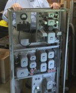
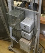
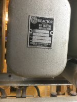
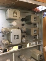
MP also built several other systems and, he was obviously not opposed to using iron in his systems. Check out these racks, the chokes and transformers appear to all be made-to-order for MP Concert Installations.
One of his most successful products was a small record player unit with a TT and a built-in amp. This unit was intended for headphone listening and was was sold to schools all across the country (I have one of these).
He also built televisions. Apparently, they were very good TVs but Mirko didn't think that new-fangled color TV fad was going to catch on.
Attachments
@Kasanay, you mentioned that the Dual 701 in the console is not working. I can highly recommend the Dual Doctor in St. Thomas Ontario Canada for a re-build. He did my Dual 1219 last year, and while it's not in the league of my Roksan Xerxes/Artimez/Shelter, it's surprisingly not nearly as far off as I thought it would be. It works perfectly and the Dual Doc was a pleasure to deal with. The cost for a typical re-build is $195 CDN. plus parts. It ended up costing me $350.00 for the 1219 resto including return shipping. Worth every penny. Just FYI
Thanks for the info!
Last edited:
Looking at the pics above, looks like Mirko really did use xfmrs abundantly. Hardly can find the tubes even. Would have been real interesting to have had a talk with him about his design ideas and opinions.
Maybe his associate is on line yet?
We need Norman Crowhurst and a bunch of the other old timers back on line. Would be interesting to compare modern design ideas and "opinions" with the past. It is remarkable that we still have tubes and xfmrs etc to build with. I'm tempted to try some massively parallel type designs with unusual tubes like 6JH8 and 12HL7 just for the fun of it, but I would never try to sell them commercially. Would never hear the end of it probably when it came to servicing them.
Last edited:
...I couldn't do any better that 3.4V....
Your plan to sort by pairs does not make enough sense to me.
I would rig a test jig. Actually I would rig the *amp* as a test jig: it's got the voltages and the trims.
Remove all 12B4. Find a handy "lower" 12B4 socket and tack a big resistor across it, to simulate a "tube".
It looks like upper and lower are identified by wire-color.
The "remove (timer) for test" is a brain fart. The timer will open quick enough, and the tubes do need to hot-up.
Now load one "upper" socket with a healthy-looking 12B4. Find a setting on the "Bias" pot to give near-zero DC voltage at the center-point as shown. Don't be precise yet. Grab another 12B4 and find its zero-bias. Do a few more and find their zeros. Set-aside any oddballs. See if there is a bias pot setting where they are all near-zero. Leave the bias pot at that position.
Test all the tubes........
I had thought: do you want an adapter to avoid socket wear? No, you have 15 identical upper sockets, rotate, you don't have to be in/out of each socket more than a few times.
Tubes within +/-4V of zero are fine.
Tubes that read + at CP are "hot"; tubes that read - at CP are "lazy".
If CP goes to -150V that tube is dead. If it goes to +150V, that tube is shorted and the test-resistor will soon smoke.
Tubes say +4V to +8V, and -4V to -8V, should be identified +/-V and, if possible, paired. Tubes outside that are dubious: mark and leave aside.
I think tubes well within 4V can all go in anywhere. They average-out to less than 4V deviation, and should bias-up and also "balance" OK.
If you have to use outliers, do it in pairs of "lazy" tubes: a -5 in upper and a -5 in lower. The "lazy" tubes may wake-up at FULL output, which is when you need it.
It is not clear to me how he set the bias pot. Monitoring the voltage at J101 assumes the tubes are nominal. We would like to break the power feed and insert a current meter. Today we can even use a Hall probe to clamp an orange or yellow wire and read DC current (H-P had a similar tool then but it was very expensive). With $9 DMMs, I would think to insert 1-Ohm resistors in those wires. (The tubes are several dozen Ohms; another Ohm makes little difference to anything.) At say 22mA per tube we expect 0.33 Amps and 0.33V across 1 Ohm. Bias sets that, on the upper bank. Balance sets the lower bank to be equal. They will be somewhat interactive. I really would not fret about several V of un-balance with four woofers series. Perhaps the market-limit is that the speaker should not "Pop" when the time relay opens (and that may mean sub-Volt balance).
Attachments
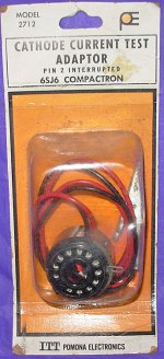
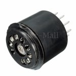
Pomona made plug in test adapters for measuring tube cathode current.
Although I haven't seen one for the 9 pin mini base. You may have to make one. There are 9 pin mini socket savers which could be dis-assembled to make one. Although I don't know how they secure the cut pin mechanically. Maybe use two of them with the pin bent out, taped together.
Although I haven't seen one for the 9 pin mini base. You may have to make one. There are 9 pin mini socket savers which could be dis-assembled to make one. Although I don't know how they secure the cut pin mechanically. Maybe use two of them with the pin bent out, taped together.
Attachments
I would rig a test jig. Actually I would rig the *amp* as a test jig: it's got the voltages and the trims.
Remove all 12B4. Find a handy "lower" 12B4 socket and tack a big resistor across it, to simulate a "tube".
Now load one "upper" socket with a healthy-looking 12B4. Find a setting on the "Bias" pot to give near-zero DC voltage at the center-point as shown. Don't be precise yet. Grab another 12B4 and find its zero-bias. Do a few more and find their zeros. Set-aside any oddballs. See if there is a bias pot setting where they are all near-zero. Leave the bias pot at that position.
Test all the tubes........
It is not clear to me how he set the bias pot.
RPP,
I seriously appreciate the amount of thought an effort you have put into this project ! This is all great info.
I understand (for the most part) the tube testing procedure that you have proposed, but, I need to clarify a couple of things:
The meter (M1) that is mounted on each amplifier is a DC current meter. It has a 500-0-500 Microamperes range.
Switch S1 is NC. When S1 is depressed (opened), M1 will display the current(voltage) across R40.
J101 is only used to read the BIAS voltage.
In my earlier post, where I talked about the offset voltage measurements, I was referring to measurements I had taken with my DMM at the speaker outputs on the fully tube-populated amps.
The following is the normal procedure for setting the BIAS and offset balance. This came to me in a note from Mathew Polk (he also owns a pair of these amps).
... If you get to the point of powering up the output section there's a small meter and a test point in the panel below the tubes. When you push the button below the meter it shows the DC offset in the output and should be set to zero. But, first check the voltage in the test point and use the Bias pot to set the bias to -20v. Then push the button to check the offset. Most likely it will pin the meter. If so, don't hold the button down, make a small adjustment with the Balance pot, push again and repeat until the meter stays in range. If you can't get the meter in range do not connect speakers as DC will be flowing through them.
I think your procedure can still be followed, we would just be reading microamperes instead of volts.
Here's a couple more questions:
What is "CP"? Checkpoint?
When we install the large resistor and first tube, then adjust the BIAS, we are adjusting the "BIAS" pot and not the "Balance" pot, right? So the BIAS voltage would not necessarily be at -20V, correct?
The value of the added resistor is not critical (something between 6.8K and 10K), right?
Thanks for your help.
Joe Y
- Status
- This old topic is closed. If you want to reopen this topic, contact a moderator using the "Report Post" button.
- Home
- Amplifiers
- Tubes / Valves
- Killer OTLs