Hi James,
There can be differences in the high frequency compensation. In rare cases, a replacement transistor will oscillate. This is more common with drivers and output transistors. You want to keep your replacement transistor reasonably close to the same gain range as the original part. Going for high fT isn't always a benefit, the same holds true for hFE.
Both those transistor types have relatively the same high frequency transition frequencies. The beta is very different though. Put up the specs for your 2SC458. Also, if you can't get a transistor easily, that takes it out of the running. There isn't any point in looking at something you can't get. If On Semi carries the part, you would have a preference to that number or numbers. With Ebay, quite a lot of transistors are remarked parts, and that makes them even less useful than a run of the mill part like a 2N3904 or something like that. So throw the fake parts out immediately if you get any. What I have seen recently are parts that are "laser etched" with betas around 200. If you look at the processing (or batch) numbers compared to the original. Your reference will always be the original parts, most of which were stamped and not etched.
-Chris
Hi Dan,
You can relax. All that coating does is tell you the transistor has been there for years. I have never seen any leakage in tests, nor excess noise. The oxide does not creep into the encapsulation either. Where those folks are getting their information from is a mystery to me. I think just imagination.
I've seen transistors that have had their faces blown clean off, and the black leads become shiny ones as soon as they enter the encapsulated area. That's pretty definitive in my book.
-Chris
Hi jerluwoo,
The only transistors that really count in a phono amplifier would be the input transistors, and the 2SC458 parts are not used in that location. They are usually found in the output sections of signal amplifiers. So the use of a low noise, high gain transistor would be incorrect in that location.
-Chris
Hmmmm....... I appreciate the sentiment but I rather like the look, sound and simplicity of this little gem.
I also really wish to keep things out of the landfill given the state of our poor earth.
It is one thing I can actually fix rather than discard - that is enough for me. It is the fixing that is as important to me as the item.
Besides my daughter thinks its cool!") That is the best endorsement actually.
That is the best endorsement actually.
James
I also really wish to keep things out of the landfill given the state of our poor earth.
It is one thing I can actually fix rather than discard - that is enough for me. It is the fixing that is as important to me as the item.
Besides my daughter thinks its cool!
That is the best endorsement actually.James
Devils' Advocate
It IS a 3$ purchase of a considered to be Low grade gear with a best forgotten past.
Bin it and move on?
No Fuss .. No muss.
Hi jerluwoo,
The only transistors that really count in a phono amplifier would be the input transistors, and the 2SC458 parts are not used in that location.
-Chris
But they are according to the schematic. Both transistors in the phono pre and the input of the power amp.
Hi jerluwoo,
Really? They aren't historically used in that location because they are general purpose transistors. You would normally see a 2SC1344 or something as the input stage.
So considering that, your suggestions make perfect sense. A 2SC1775A or 2SC2440 (?) would be my choices - if you can find the real parts.
-Chris
Question: I pulled all four of the 2sc458 from the pre board and tested them with my Peak DCA55. They all tested fine with no leakage and consistent HFE.
I have replaced all caps on the pre board with caps I had on hand from other projects. Does it make any sense to reinstall the 458s and see if problem solved? Oh, and I replaced the power supply caps too.
James
I have replaced all caps on the pre board with caps I had on hand from other projects. Does it make any sense to reinstall the 458s and see if problem solved? Oh, and I replaced the power supply caps too.
James
It's fine to reinstall and test but you need to isolate the preamp from the rest of the amp to determine the pre is not the issue. Tapping in at the input to the volume pot and feeding the signal to a known quiet amp to see if the pre is still making noise or not and then again after the tone amp to isolate where the noise starts.
Thanks Jerluwoo. The amp bypasses the preamp board when using the tuner/aux inputs. Those sound clean and strong. I accidentally pulled some wires out of the selector switch from the pre-board to the switch that I am working through now. I took pictures but the part I need to see is blurry - of course.
It is always something it would seem. I keep reminding myself that the journey is as important as the destination.
James
It is always something it would seem. I keep reminding myself that the journey is as important as the destination.
James
reinstall issue
Hi, I have reinstalled the 2sc458s after they all tested fine with my tester. In the process I inadvertently pulled the wires from the Tuner/Phono1/Phono2/Aux selector switch.
Thinking ahead I had taken pictures but of course the one of the selector switch is unclear as to where four wires go from the pre-amp board to the selector.
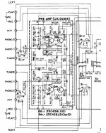
The way I read the schematic (excerpt attached), the wire that exits the pre board at C16 is also connected to the wire that exits the pre board at C6, then both go to the selector. The other side is a mirror with C17 and C4 going to the selector.
I see no numbers on the selector switch and have been unsuccessful at guessing which ones are to be connected. The designation on the schematic for the switch is S1-1l and S-1-2r
Am I being stupid? Wait, don't answer that.
Thanks.
Hi, I have reinstalled the 2sc458s after they all tested fine with my tester. In the process I inadvertently pulled the wires from the Tuner/Phono1/Phono2/Aux selector switch.
Thinking ahead I had taken pictures but of course the one of the selector switch is unclear as to where four wires go from the pre-amp board to the selector.
The way I read the schematic (excerpt attached), the wire that exits the pre board at C16 is also connected to the wire that exits the pre board at C6, then both go to the selector. The other side is a mirror with C17 and C4 going to the selector.
I see no numbers on the selector switch and have been unsuccessful at guessing which ones are to be connected. The designation on the schematic for the switch is S1-1l and S-1-2r
Am I being stupid? Wait, don't answer that.
Thanks.
Thanks
Hi, now that makes sense. Great idea and I will try thatI have been partially successful in getting one side to work intermittently. In reading the schematic it seems clear to me that each side has two wires the exit the pre-board. Each set of two I think get connected to each side of the selector switch. I have one side working and I have connected it with an alligator clip wire. Using insulated needle-nose pliers holding the other end I can touch the terminal on the selector and get audio. With the wires for side that is working, I get clean audio on each side of the selector and each speaker comes to life alternatively.
However, the other side of the preboard which is a mirror image does not make audio. Have to go back and check it all again I guess.
Thanks for the tip on the tape out that will help a lot.
James
With the selector set to phono there should be continuity from the tape record outputs and the terminals the pre should connect to.
Hi James,
You can do a similar thing with your finger on the selector switch terminals and hear hum for each selection on your input selector switch. You might find that is easier to do.
I can't believe that you didn't damage the switch! Amazing luck! Just work at a steady pace and you should get through it okay.
-Chris
I have been referred to as a Bull In A China Shop on more than one occasion I must say. I may very well have caused some minor damage to the switch - it is old and fragile. So, I am being very careful with my bull hooves in working with it.
I do believe I am lucky and just need to revisit each and every solder point on the non-working side of the preboard. I am concerned that I am not reading the schematic right though.
I attached it above because I do not understand the theory behind why the two wires for each side connect just before reaching the switch connection. If they connect they must both be carrying a positive signal? Where is the ground?
I have books on this stuff and promise I have read them but I actually do not learn it well until I am applying it.
I know this is an old cheap amp but it is very gratifying to keep her going. With the new PS caps it sounds really good through the tuner/aux inputs for such a little gal.
Hi James,
Your audio signals are all referenced to "ground", so since all the common part of the audio inputs are all connected together (in common), you just need to route the "hot" terminal of the jacks that carry the signals. If you were using a balanced type of system internally, you would need to switch both conductors.
Your question isn't a silly one and we all have to learn that at some point in our lives. Just remember that wee don't tend to draw in the common connections in a conventional diagram as it would only clutter up the schematic and make it harder to follow.
-Chris
I could not seem to get the right side to work. I have tested and compared all connections good side/bad side. The two 2sc458 transistors all test fine with my Peak tester but I am getting no audio from that side.
While playing an LP on the TT, if I took the good side pre outputs connected with an alligator clip and touch either side of the selector switch I get strong audio on both right and left channels. That told me that downstream is fine.
Assuming it was possible that transistors that tested fine are actually not I dug around in my parts bin and came across a set of four NTE193 (gasp) which are roughly equivalent to a 2sc1845 which in turn is a higher voltage version of 2sc1815 which is I think a direct replacement for the 2sc458. Put them in and voila! Audio both sides clean and strong.
The cool thing for me is I spent no extra money and used parts I had on hand albeit roughly equivalent and now it works. It has more bass punch than it did before. The power filter cap went from 2000 to 3300uf.
Thanks All! I am going to button it up and listen to my little 13 watt wonder for a while.
James
- Status
- This old topic is closed. If you want to reopen this topic, contact a moderator using the "Report Post" button.
- Home
- Amplifiers
- Solid State
- Kicking It with a Kenwood KA-2000!